MN.00273.E - 004 61
A good set of the thresholds is to put the ATPC Low Level threshold higher (or even slightly higher) than
the threshold of the highest modulation scheme of the ACM; this way, the ATPC start to work before than
the received signal is reduced and by consequence will force the system to downgrade the modulation. The
behaviour of the system is to always try to increase the PTX and so the System Gain, before than being
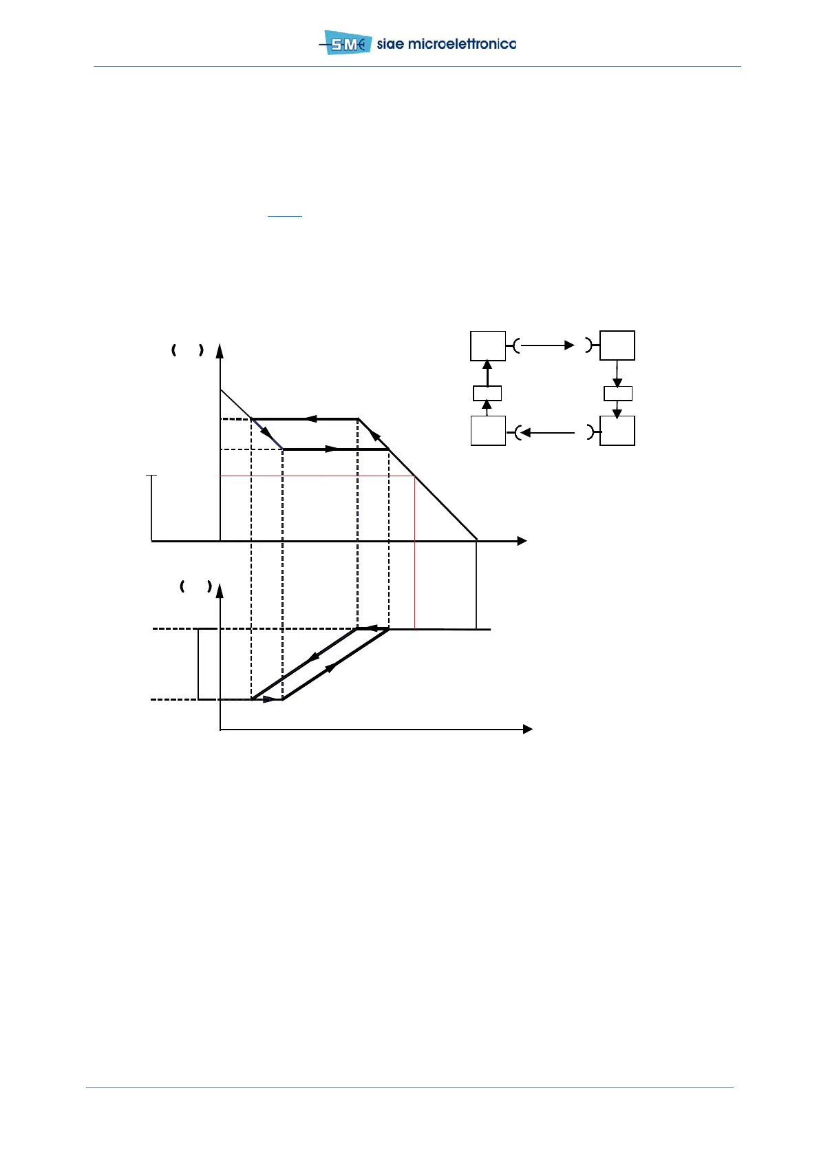
forced to reduce capacity due to modulation downgrade.
Resuming, the correct setting of the thresholds is when the two windows, the ATPC one and the ACM one,
are not overlapped, as per Fig.18
.
Fig.18 - ATPC diagram
Thresh High
Thresh Low
Hop attenuation (dB)
ATPC range
PTx max.
PTx min.
Remote PRx
dBm
Local PTx
dBm
Hop attenuation (dB)
Tx
Rx
Rx
Tx
PTx actuation
Local
Remote
PRx recording
Transmission
of PTx control
µ
P
µ
P
level
PTx control
ACM
range
Threshold
highest ACM
profile
 Loading...