SMA America, LLC 10 Troubleshooting
Installation Manual SB30-40-US-IA-en-33 63
10 Troubleshooting
10.1 LED Signals
The LEDs represent the current operating state of the inverter clarify the messages in the display by
means of the various blink codes.
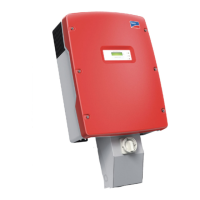
Figure 25: Position of the LEDs
Position Designation Status Explanation
A Green LED Glowing Operation
Indicates standard operation of the inverter.
Blinks 3 times per
second
Start
The inverter is calibrating internal systems. The
calibration takes 10 s. Following successful
calibration, the inverter resumes normal
operation.
Stop
The inverter has been manually set to stop
mode.
Blinks once per
second
Waiting
The inverter is monitoring the grid limits and
the DC voltage of the PV array. If both values
meet the feed-in conditions, the inverter begins
feeding into the power distribution grid.
Goes out briefly
once per second
Derating
The inverter reduces the power in order to
protect the internal components from
overheating.
 Loading...