7 Electrical Connection
SMA Solar Technology AG
Operating Manual STPx0-3SE-40-BE-en-10 37
7 Electrical Connection
7.1 Overview of the Connection Area
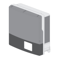
Figure 13: Connection areas at the bottom of the inverter
Position Designation
A 1 positive and 1 negative DC connector (type: Sunclix), input A
B 1 positive and 1 negative DC connector (type: Sunclix) for Sunny Tripower
5.0 SE, 6.0 SE and 8.0 SE, 2 positive and 2 negative DC connectors (type:
Sunclix) for SunnyTripower 10.0 SE, input B
C 1 positive and 1 negative DC connector for battery (type: Multi-Contact MC4)
connection
D Network port with protective cap
E Jack with protective cap for the WLAN antenna
F
CAN & DIG-I/O socket with protective cap for connection of COM connec-
tor
G
AC-BACKUP socket with protective cap for connection of AC backup loads.
The protective cap may only be removed when backup loads are connected.
H
AC-GRID socket with protective cap for AC grid connection
I Connection point for an additional grounding
7.2 AC Connection
7.2.1 Requirements for the AC Connection
AC cable requirements as follows:
☐ Conductor type: copper wire (flexible)
☐ External diameter: 14mm to 25mm
☐ Conductor cross-section: 1.5mm² to 10mm²

 Loading...