MGC300 Genset Controller User Manual
MGC300 Genset Controller Version 1.1 2020-01-04 Page 15 of 27
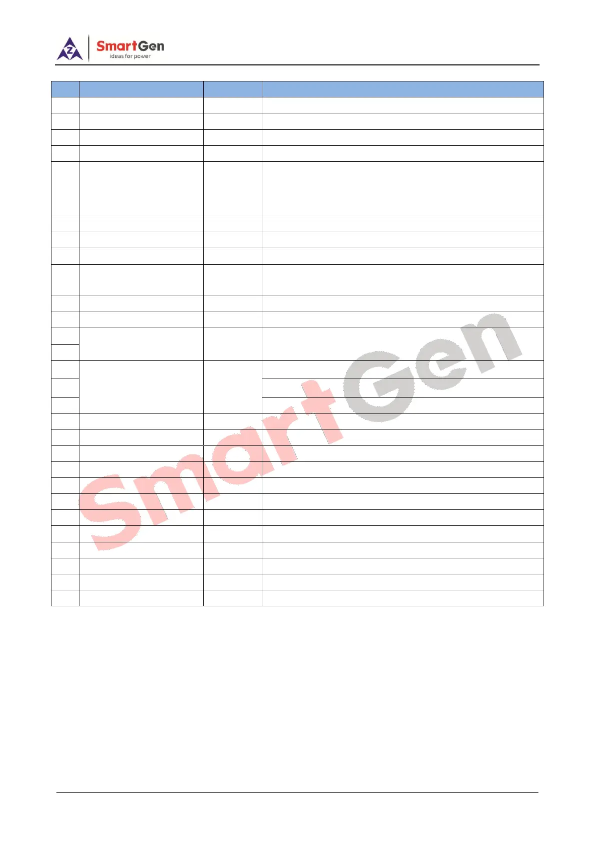
Table 6 Terminal Connection Description
Connected with negative of starter battery.
Connected with positive of starter battery.
B+ power is supplied by terminal 2, rated 7A.
B+ power is supplied by terminal 2, rated 7A.
Digital input; GND connected is active (B-);
Level sensor; connected with level low signal or level
resistance sensor;
GND connected is active (B-);
Connected with digital signals of oil pressure low;
Connected with water/cylinder digital signals or temp.
resistance sensor;
Relay N/O connector, volt free output, rated 7A;
Connected to Mains R Phase;
Connected to Mains S Phase;
Connected to Mains T Phase;
Connected to Mains N wire;
Connected to genset output U Phase;
Connected to genset output V Phase;
Connected to genset output W Phase;
Connected to genset output N wire;
Outside connected with CT secondary coil (rated 62.5mA);
Outside connected with CT secondary coil (rated 62.5mA);
Outside connected with CT secondary coil (rated 62.5mA);