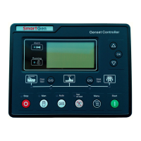
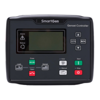
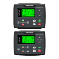
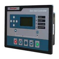
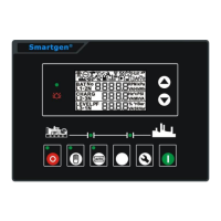
HGM6100U Series Automatic Control Module
HGM6100U Automatic Genset Controller ISSUE 2014-10-28 Version 1.2 Page 18 of 39
No. Function Cable Size Description
11 volt-free contact output
16 A rated
12
Aux. Relay Output 4 2.5mm
2
13
14
Charging Generator D+
Input
1.0mm
2
Connect to D+ (WL) terminal. If without,
the terminal is not connected.
15 Speed sensor input
0.5mm
2
Connected to Speed sensor, shielding
line is recommended.
16
Speed sensor input, B-
is connected.
17
Temp. Sensor Input
1.0mm
2
Connect to water
/cylinder temp.
resistance type sensor
Reference
table 4
18
Oil Pressure Sensor
Input
1.0mm
2
Connect to oil pressure
resistance type sensor
19
Liquid Level Sensor
Input
1.0mm
2
Connect to liquid level
resistance type sensor
20 Configurable Input 1 1.0mm
2
Ground connected is
active (B-)
Reference
table 3
21 Configurable Input 2 1.0mm
2
Ground connected is
active (B-)
22 Configurable Input 3 1.0mm
2
Ground connected is
active (B-)
23
CT A Phase Sensing
Input
1.5mm
2
Connect secondary coil, rated 5A
24
CT B Phase Sensing
Input
1.5mm
2
Connect secondary coil, rated 5A
25
CT C Phase Sensing
Input
1.5mm
2
Connect secondary coil, rated 5A
26 CT Common Port 1.5mm
2
Refer to INSTALLATION description.
27
Generator U phase
Voltage
Sensing Input
1.0mm
2
Connect to U phase output(2A fuse is
recommended)
28
Generator V phase
Voltage sensing Input
1.0mm
2
Connect to V phase output(2A fuse is
recommended)
29
Generator W phase
Voltage Sensing Input
1.0mm
2
Connect to W phase output(2A fuse is
recommended)
30 Generator N2 Input 1.0mm
2
Connect to generator N-wire
31
Mains R phase Voltage
Sensing Input
1.0mm
2
Connect to mains R phase(2A fuse is
recommended) HGM6110UC without
32
Mains S phase Voltage
Sensing Input
1.0mm
2
Connect to mains S phase (2A fuse is
recommended) HGM6110UC without.
33
Mains T phase Voltage
Sensing Input
1.0mm
2
Connect to mains T phase, (2A fuse is
recommended) HGM6110UC without.
 Loading...
