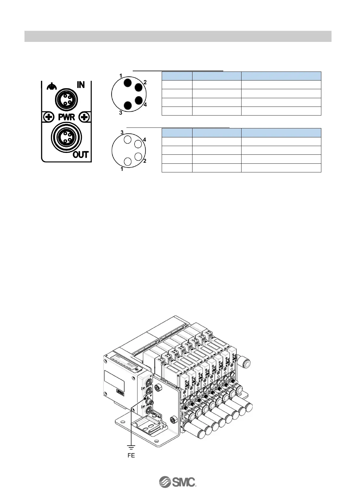
Fig 2-3. Pin allocation of power connector
The power-supply line for logic/input and power-supply line for output are isolated. Be sure to supply power
respectively. Either two different power supplies or a single-source power supply can be used.
NOTE
The recommended tightening torque is 0.2 Nm for communication / power connectors.
Unused communication / power connectors must be fitted with seal caps to ensure dustproof and
waterproof performance (protection class) of the product.
Power supply PWR for logic/input and PWR(V) for output should be protected by an external fuse.
2.3. FE terminal
The SI Unit must be connected to FE (Functional Earth) to divert electromagnetic interference.
Connect a grounding cable from the FE terminal screw on the SI Unit to the nearest functional earth point.
The grounding cable should be as thick and short as reasonably possible.
The recommended tightening torque for the FE terminal is 0.3 Nm.
Fig 2-4. FE terminal