FLEXIBLE ASSEMBLY SYSTEM FAS200
User Manual for FAS200 - 11 -
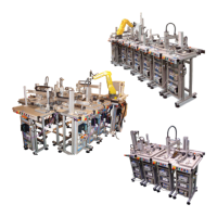
The process modules function either independently of the transport system, in
in single or couple modes, or integrated into it, in cell mode. The modules are
located in a side of the linear transfer, and may be withdrawn for re-positioning
in a different order (the repositioning of different modules of the system can
mean repositioning of stoppers, lifters-positioners and reprogramming of the
controllers of the system), moved for future extensions or work in
completely independent, in a single mode, or with its complementary module in
a couple mode (requiring reprogramming of the control).
Figure 9: FAS201 module a single mode. Figure 10: FAS201 and FAS202
modules in couple module (without any
linear transfer).
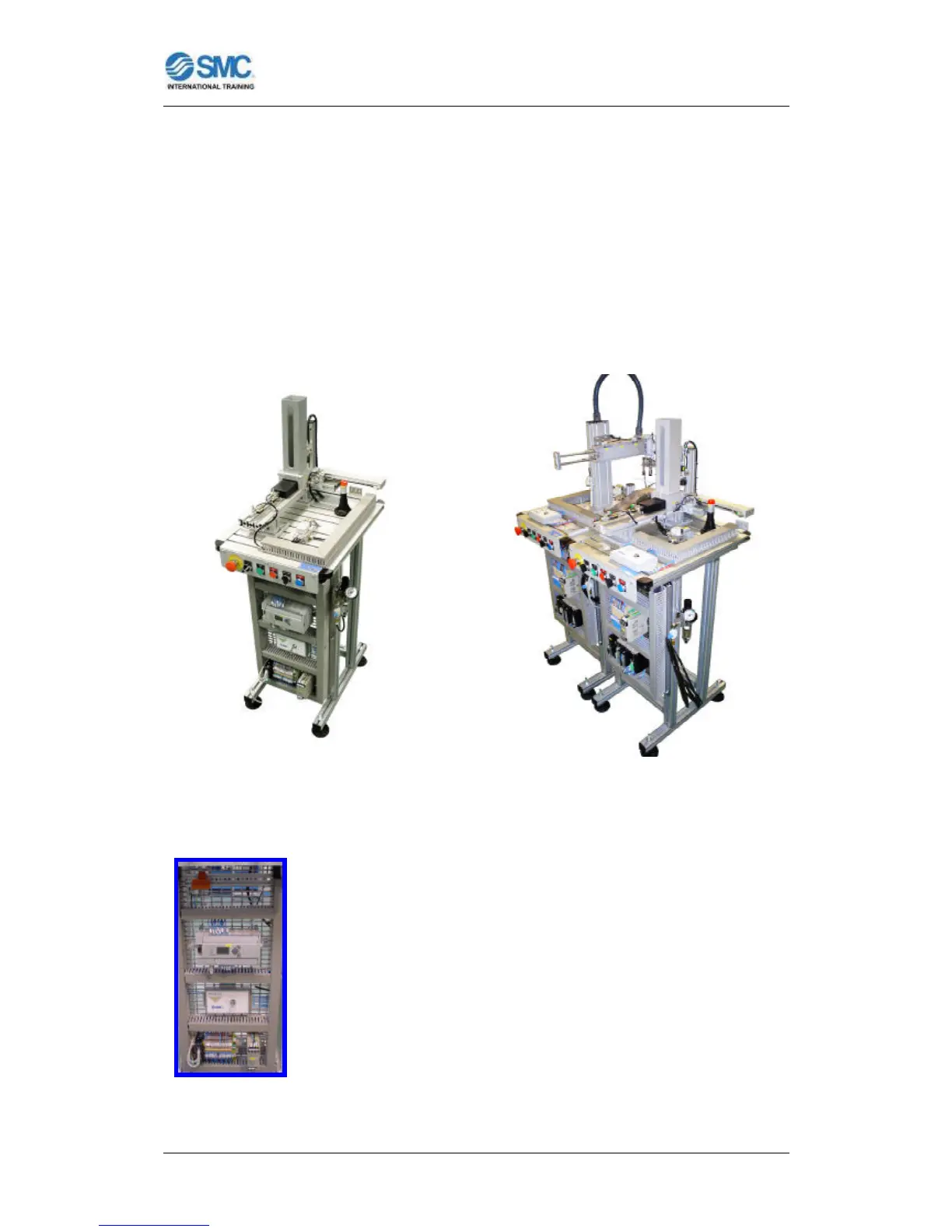
Each station has its own electrical panel, where the wiring
system and PLC are fully visible for study, while new elements
may be fitted to the panel if desired. In addition, students may
design and build their own controls with different PLCs and
subsequently integrate them in the station, thereby developing
a further series of skills envisaged in the Training Cycles for
those persons who form the target group for the Cell.
Figure 11: Electrical
panel of a module.
 Loading...