2 About this product
-14-
No.PS※※-OMW0009-A
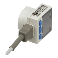
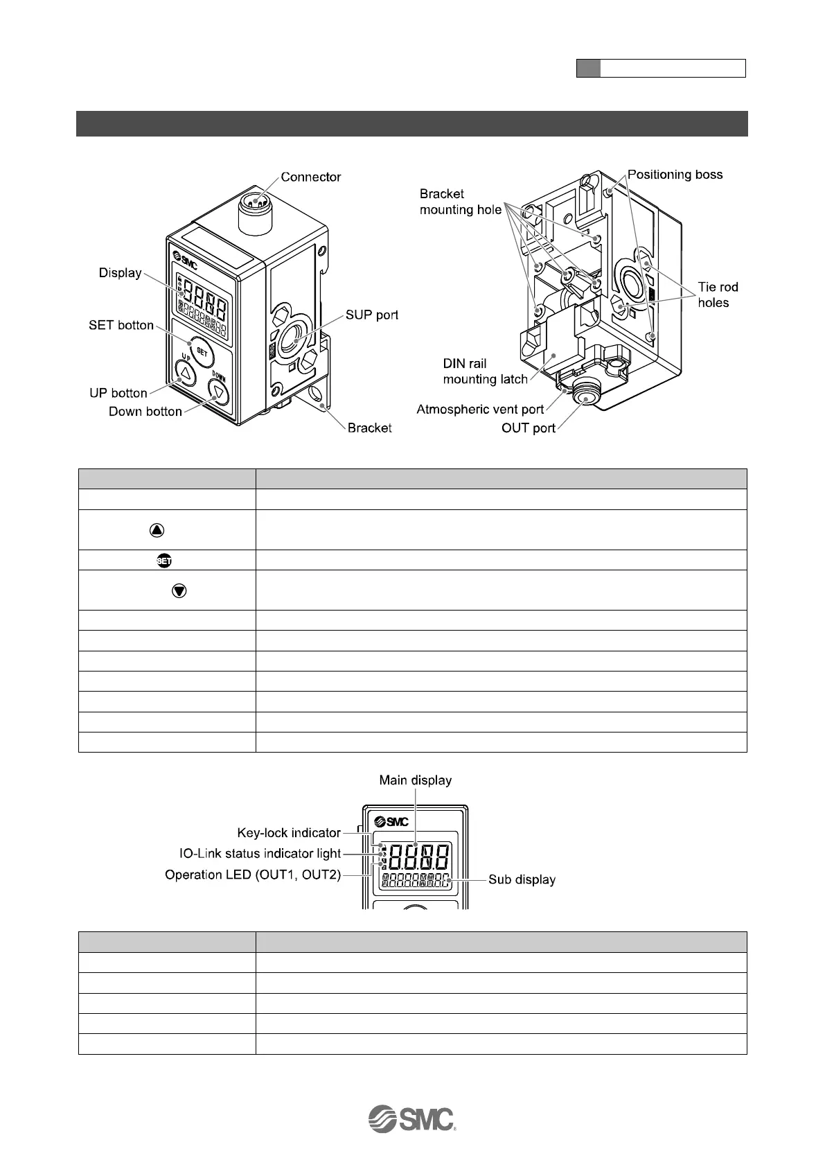
Summary of Product parts
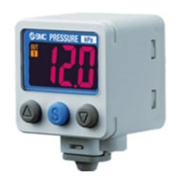
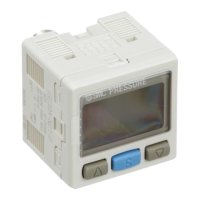
Selects the mode and the display shown on the sub display, or increases the switch
point.
Press this button to change the mode and to fix the settings.
Selects the mode and the display shown on the sub display, or decreases the switch
point.
Used to attach the bracket to the product.
Used to connect additional products.
OUT port (Detection port)
Port to be connected to the detection nozzle.
Port to vent exhaust air to the atmosphere.
Used to mount the product on a DIN rail.
ON/OFF, display value and error code are displayed. (2 colour display)
Indicates the switch output status. Turns ON (orange) when the switch output is ON.
Level meter, display value, switch point, pressure etc. are displayed.
Turns ON when keys are locked.
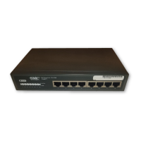
IO-Link status indicator light
LED is ON when OUT1 is used in IO-Link mode. (LED is OFF in SIO mode)
 Loading...