4 How to use
-86-
No.PS※※-OMW0009-A
Other Settings
○Snap shot function
The current display value can be stored to the switch output ON/OFF set point.
When the of Sub display (left) items listed below are selected in the 3 step setting mode, Simple setting
mode or Setting of each function mode ([F 1] OUT1, [F 2] OUT2 setting), by pressing the UP and DOWN
buttons simultaneously for 1 second or longer, the set value of the sub display (right) shows [- - - ], and the
values corresponding to the current pressure values are automatically displayed.
Detection distance (guideline)
Detection distance (guideline)
Detection distance (guideline)
Detection distance (guideline)
•Set value
The value is set to the same value as the display value (current displayed value).
(There is a range which cannot be set to the current displayed value depending on the hysteresis. In that
case, the value is set to the closest value).
•Hysteresis
The hysteresis is calculated from the equation below and set.
Normal output: (set value) - (Current display value)
Reverse output: (Current display value) - (set value)
If the calculation result becomes 0 or less, [Err] is displayed on the sub display (right) and the set value is
not changed.
Afterwards, it is possible to adjust the value by pressing the UP or DOWN button.
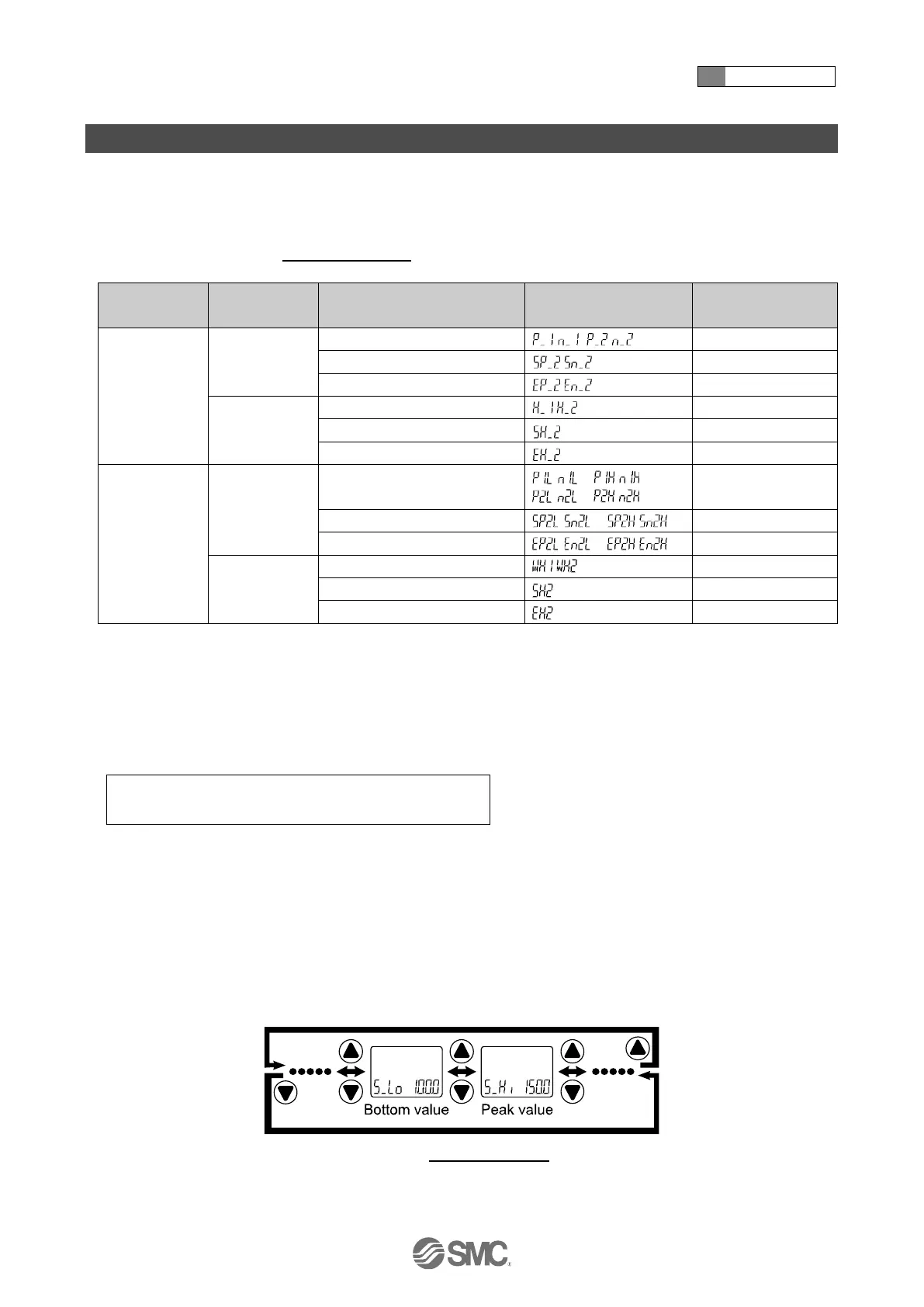
○Peak/bottom value indication
The maximum (minimum) pressure on the SUP port side when the power is supplied is detected and updated.
In peak/bottom indication mode, the current pressure is displayed.
Press the UP or DOWN button in measurement mode to switch the sub-display (left) to the display shown below.
When the SET and DOWN buttons are pressed for 1 second or longer simultaneously while the peak/bottom
values are displayed, the sub display (right) displays [- - -] and the maximum (minimum) pressure value are cleared.
 Loading...