2 About this product
-20-
No.PS※※-OMW0009-A
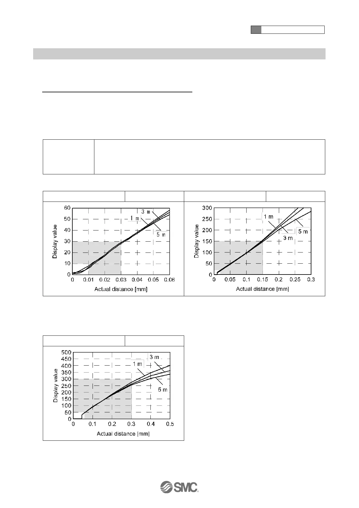
○Relationship between the display value (switch point) and distance
The graphs below show the relationship between [display value (switch point) on the sub display] and [the
actual distance between the detection surface and the workpiece].
Relationship between the display value and the distance
These graphs show the relationship between the display value and the distance.
1: The values in the table are for reference only). The values will vary depending on the individual product difference and nozzle
machining dimensions.
2: The zero cut function displays 0 forcibly when the value is below the set value. Within the zero cut-off range, it is possible to
change the value to 0, but even though the distance between the hole and workpiece is in close contact with each other, it might
not be able to make the display 0.
Detection nozzle: ø1.5
Piping: F type: ø4 x ø2.5 tube 1 m, 3 m, 5 m
G, H type: ø6 x ø4 tube 1 m, 3 m, 5 m
Supply pressure: 200 kPa
Piping length: 1m, 3m, 5m
Piping length: 1m, 3m, 5m
: In the default condition, the value can be displayed as 0.
: In the default condition, when the distance is below 9, 0 will
be displayed.
Piping length: 1m, 3m, 5m
: In the default condition, when the distance is below 30, 0 will
be displayed.
 Loading...