4 How to use
-45-
No.PS※※-OMW0009-A
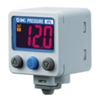
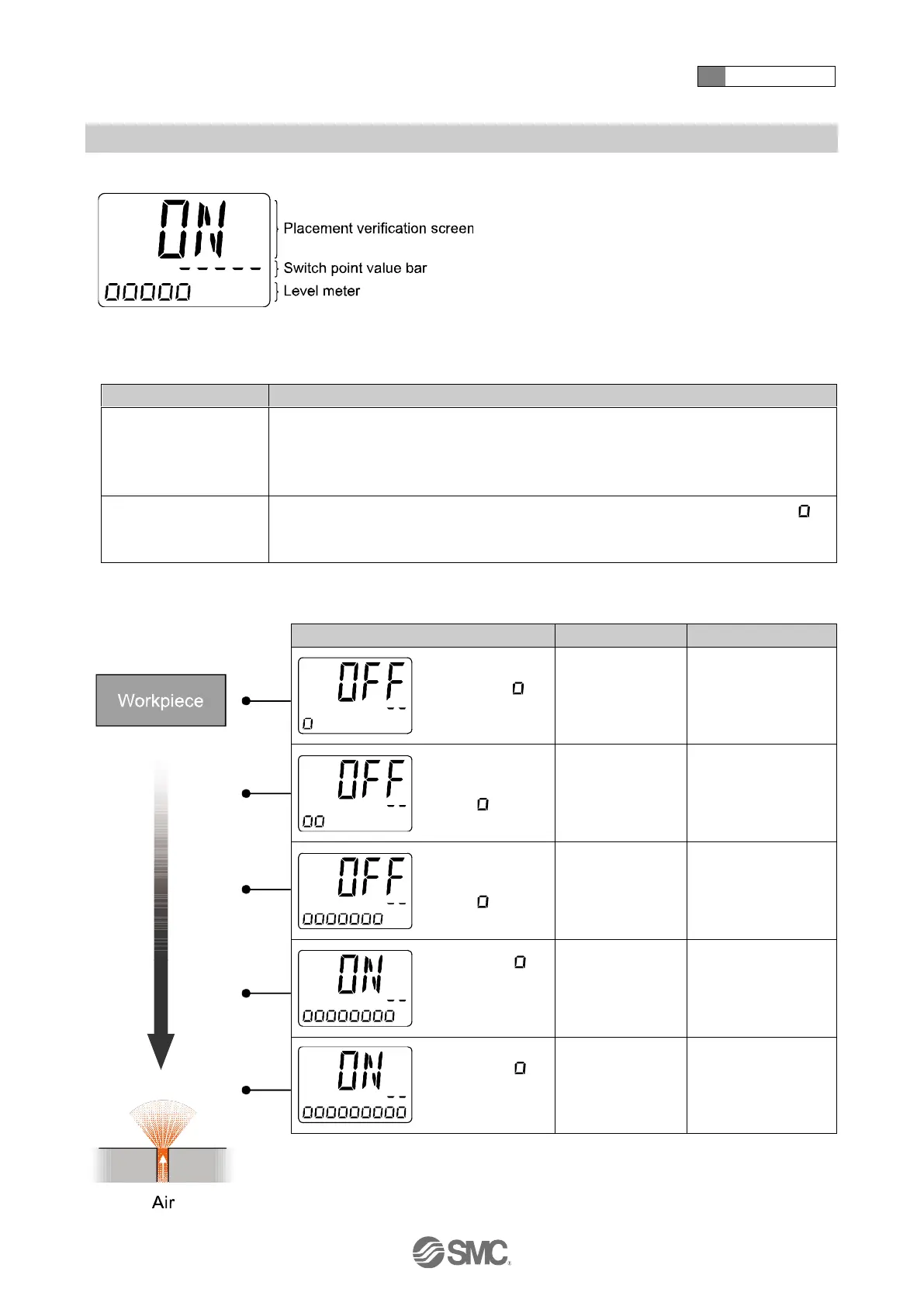
■Measurement mode
Placement verification screen (Main display)
The Placement condition is indicated by the switch output status (ON/OFF).
Level meter (Sub display)
When OUT1 is set to hysteresis mode, the bar equivalent to the switch point, which has
been set as the set value of OUT1, is displayed automatically.
: OUT1 switch point only When OUT1 is set to window comparator mode, the bar will not be
displayed.
The workpiece gap condition approaching the nozzle is indicated by the number of "
.
"
displayed.
This display is a reference only. It is not an accurate distance measurement.
○Relationship between the display and the placement status
(e.g.: hysteresis mode, reversed output)
Level meter " " is
not displayed.
Detection surface
and the workpiece
are very distant.
Switch point value
bar "- -" and level
meter " " are not
close.
Detection surface
and the workpiece
are too far apart.
Switch point value
bar "- -" and level
meter " " are
close.
Detection surface
and the workpiece
are slightly apart.
Level meter " "
has reached
switch point value
bar "- -".
Workpiece is
placed on the
detection surface.
Level meter " "
reaches its
maximum.
Workpiece is in
close contact with
the detection
surface.
: For normal output, the switch point is displayed on the left side.
Placement surface
(Detection nozzle)
 Loading...