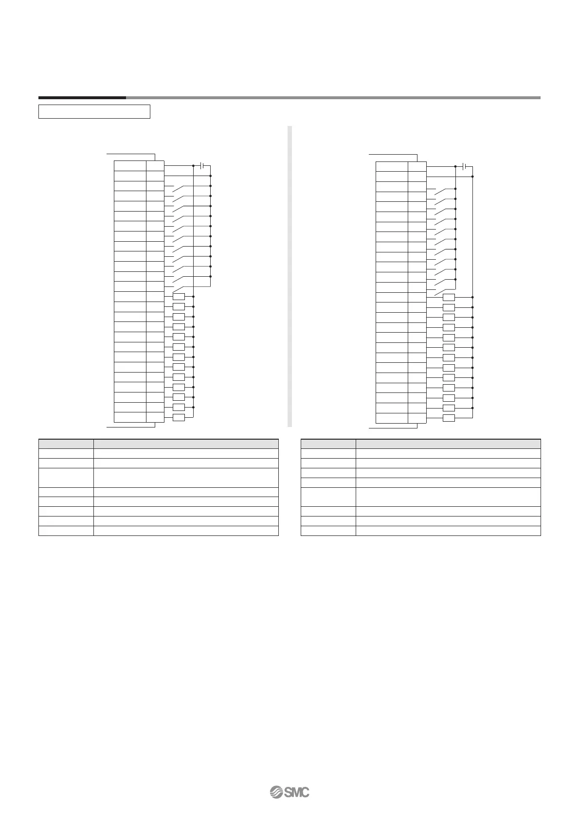
Wiring Example
Parallel I/O Connector
Wiring diagram
JXC51- (NPN)
JXC61- (PNP)
Input Signal Output Signal
∗ When you connect a PLC to the parallel I/O connector, use the I/O cable (LEC-CN5-).
∗ The wiring changes depending on the type of parallel I/O (NPN or PNP).
∗1 Signal of negative-logic circuit (N.C.)
Name Details
OUT0 to OUT5 Outputs the step data no. during operation
BUSY Outputs when the actuator is moving
AREA Outputs within the step data area output setting range
SETON Outputs when returning to origin
INP
Outputs when target position or target force is reached
(Turns on when the positioning or pushing is completed.)
SVRE Outputs when servo is on
∗ESTOP
∗
1
OFF when EMG stop is instructed
∗ALARM
∗
1
OFF when alarm is generated
Name Details
COM+ Connects the power supply 24 V for input/output signal
COM− Connects the power supply 0 V for input/output signal
IN0 to IN5
Step data specified bit no.
(Input is instructed by combining IN0 to 5.)
SETUP Instruction to return to origin
HOLD Temporarily stops operation
DRIVE Instruction to drive
RESET Resets alarm and interrupts operation
SVON Servo ON instruction
COM+
COM−
IN0
IN1
IN2
IN3
IN4
IN5
SETUP
HOLD
DRIVE
RESET
SVON
OUT0
OUT1
OUT2
OUT3
OUT4
OUT5
BUSY
AREA
SETON
INP
SVRE
∗ESTOP
∗ALARM
CN5
A1
A2
A3
A4
A5
A6
A7
A8
A9
A10
A11
A12
A13
B1
B2
B3
B4
B5
B6
B7
B8
B9
B10
B11
B12
B13
COM+
COM−
IN0
IN1
IN2
IN3
IN4
IN5
SETUP
HOLD
DRIVE
RESET
SVON
OUT0
OUT1
OUT2
OUT3
OUT4
OUT5
BUSY
AREA
SETON
INP
SVRE
∗ESTOP
∗ALARM
A1
A2
A3
A4
A5
A6
A7
A8
A9
A10
A11
A12
A13
B1
B2
B3
B4
B5
B6
B7
B8
B9
B10
B11
B12
B13
CN5
11
JXC51/61 Series
Power supply 24 VDC
for I/O signal
Power supply 24 VDC
for I/O signal
Load
Load
Load
Load
Load
Load
Load
Load
Load
Load
Load
Load
Load
Load
Load
Load
Load
Load
Load
Load
Load
Load
Load
Load
Load
Load
 Loading...


