300
300
300051
32
(22.4)
(14.4)
L
B1 A1
B13 A13
A1
xx
B13
A13
B1
(Ø 8.9)
Options
Conversion cable P5062-5 (Cable length: 300 mm)
I/O Cable
∗
To connect the teaching box (LEC-T1 -3G) or communication cable for
controller setting (LEC-W 2 A-C) to the controller, a conversion cable is
required.
<Applicable cable size>
AWG20 (0.5 mm
2
), cover diameter
2.0 mm or less
Communication cable for controller setting
Hardware Requirements
q Communication cable JXC-W2A-C
<Controller setting software/USB driver>
· Controller setting software
· USB driver (For JXC-W2A-C)
Download from SMC’s website: https://www.smc.eu
∗ It can be connected to the controller directly.
w USB cable LEC-W2-U
∗ Windows
®
7, Windows
®
8.1, and Windows
®
10 are registered
trademarks of Microsoft Corporation in the United States.
OS Windows
®
7, Windows
®
8.1, Windows
®
10
Communication interface
USB 1.1 or USB 2.0 ports
Display 1024 x 768 or more
A set which includes a communication cable (JXC-W2A-C) and
a USB cable (LEC-W2-U)
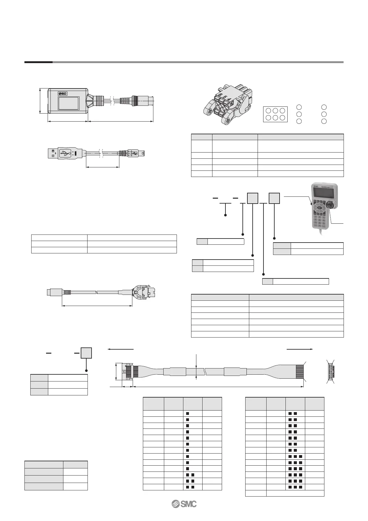
e Controller setting kit JXC-W2A
Power supply plug
JXC-CPW
∗ The power supply plug is an accessory.
Power supply plug
Terminal name
Function Details
0V Common supply (–)
The M24V terminal, C24V terminal, EMG
terminal, and LK RLS terminal are common (–).
M24V
Motor power supply (+)
Motor power supply
(+)
of the controller
C24V
Control power supply (+)
Control power supply
(+)
of the controller
EMG Stop (+)
Connection terminal of the external stop circuit
LK RLS Lock release (+)
Connection terminal of the lock release switch
6
3
5
2
4
1
40V
2 M24V
1 C24V
5 N.C.
3 EMG 6 LK RLS
Teaching box
LEC
T1 3
J
G
Teaching
box
Initial language
J
Japanese
E
English
∗
The displayed language can be
changed to English or Japanese.
Cable length [m]
3
3
Specifications
Item Description
Switch Stop switch, Enable switch (Option)
Cable length [m] 3
Enclosure IP64 (Except connector)
Operating temperature range [°C]
5 to 50
Operating humidity range [%RH]
90 or less (No condensation)
Weight [g] 350 (Except cable)
Stop switch
G
Equipped with stop switch
Enable switch
—
None
S
Equipped with enable switch
∗ Interlock switch for jog and test
function
LEC CN5 1
Cable length (L) [m]
∗ Conductor size: AWG28
Connector
pin no.
Insulation
colour
Dot
mark
Dot
colour
B1 Yellow Red
B2
Light green
Black
B3
Light green
Red
B4 Grey Black
B5 Grey Red
B6 White Black
B7 White Red
B8
Light brown
Black
B9
Light brown
Red
B10 Yellow Black
B11 Yellow Red
B12
Light green
Black
B13
Light green
Red
— Shield
Connector
pin no.
Insulation
colour
Dot
mark
Dot
colour
A1
Light brown
Black
A2
Light brown
Red
A3 Yellow Black
A4 Yellow Red
A5
Light green
Black
A6
Light green
Red
A7 Grey Black
A8 Grey Red
A9 White Black
A10 White Red
A11
Light brown
Black
A12
Light brown
Red
A13 Yellow Black
1
1.5
3
3
5
5
Weight
Product no. Weight [g]
LEC-CN5-1
170
LEC-CN5-3
320
LEC-CN5-5
520
16
Controller (Step Data Input Type)
JXC51/61 Series
Controller side PLC side
(Terminal no.)
Enable switch
(Option)
Stop
switch
 Loading...


