∗ Numerical values other than “Moving force,” “Area 1,” and “Area 2” can be used to perform operation under numerical instructions from JXCL.
Specifi cations
Model
JXCE1 JXC91 JXCP1 JXCD1 JXCL1 JXCLF JXCM1
Network EtherCAT EtherNet/IP™ PROFINET DeviceNet
®
IO-Link CC-Link
Compatible motor Step motor (Servo/24 VDC)
Power supply Power voltage: 24 VDC ±10%
Current consumption (Controller)
200 mA or less 130 mA or less 200 mA or less 100 mA or less 100 mA or less 100 mA or less
Compatible encoder Incremental/Battery-less absolute
Communication specifi cations
Applicable
system
Protocol EtherCAT
∗
2
EtherNet/IP™
∗
2
PROFINET
∗
2
DeviceNet
®
IO-Link CC-Link
Version
∗
1
Conformance Test
Record V.1.2.6
Volume 1 (Edition 3.14)
Volume 2 (Edition 1.15)
Specifi cation
Version 2.32
Volume 1 (Edition 3.14)
Volume 3 (Edition 1.13)
Version 1.1
Port Class A
Ver. 1.10
Communication
speed
100 Mbps
∗
2
10/100 Mbps
∗
2
(Automatic
negotiation)
100 Mbps
∗
2
125/250/500 kbps
230.4 kbps
(COM3)
156 kbps, 625 kbps,
2.5 Mbps, 5 Mbps,
10 Mbps
Confi guration fi le
∗
3
ESI fi le EDS fi le GSDML fi le EDS fi le IODD fi le CSP+ fi le
I/O occupation area
Input 20 bytes
Output 36 bytes
Input 36 bytes
Output 36 bytes
Input 36 bytes
Output 36 bytes
Input 4, 10, 20 bytes
Output 4, 12, 20, 36 bytes
Input 14 bytes
Output 22 bytes
1 station, 2 stations,
4 stations
Terminating resistor Not included
Memory EEPROM
LED indicator
PWR, RUN, ALM, ERR
PWR, ALM, MS, NS
PWR, ALM, SF, BF
PWR, ALM, MS, NS
PWR, ALM, COM
PWR, ALM, L ERR, L RUN
Cable length [m] Actuator cable: 20 or less
Cooling system Natural air cooling
Operating temperature range [°C]
0 to 55 (No freezing)
∗
4
Operating humidity range [%RH]
90 or less (No condensation)
Insulation resistance [MΩ]
Between all external terminals and the case: 50 (500 VDC)
Safety function — — STO, SS1-t —
Safety standards ——
EN 61508 SIL 3
∗
5
EN 62061 SIL CL 3
∗
5
EN ISO 13849-1 Cat. 3 PL e
∗
5
—
Weight [g]
Screw mounting
220 210 220 210 190 220 170
DIN rail mounting
240 230 240 230 210 240 190
∗1 Please note that versions are subject to change.
∗2 Use a shielded communication cable with CAT5 or higher for the PROFINET, EtherNet/IP™, and EtherCAT.
∗3 The fi les can be downloaded from the SMC website.
∗4 The operating temperature range for both controller version 1 products and controller version 2 products is 0 to 4 0 °C. Refer to the Web Catalogue for
details on identifying controller version symbols.
∗5 The above safety integrity level is the max. value. The achievable level varies depending on the confi guration and inspection method of the component.
Be sure to refer to “Safety Manual: JXC#-OMY0009” for more information.
Trademark
EtherNet/IP
®
is a registered trademark of ODVA, Inc.
DeviceNet
®
is a registered trademark of ODVA, Inc.
EtherCAT
®
is registered trademark and patented technology, licensed by Beckhoff Automation GmbH, Germany.
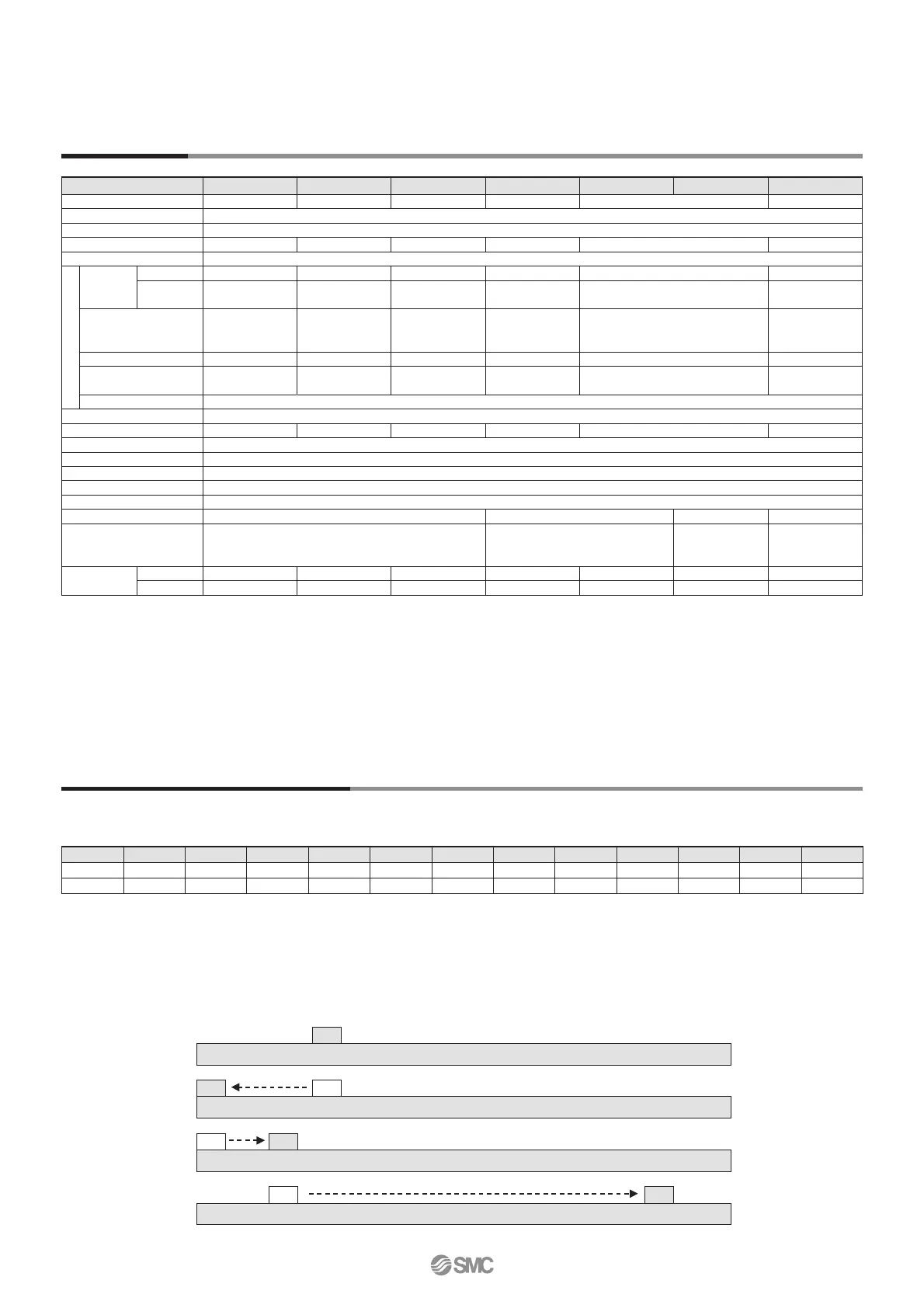
Example of Operation Command
In addition to the step data input of 64 points maximum in each communication protocol, the changing of each parameter can be performed in real time via numerical data defi ned operation.
<Application example> Movement between 2 points
No.
Movement mode
Speed Position
Acceleration
Deceleration
Pushing force
Trigger LV
Pushing speed
Moving force
Area 1 Area 2 In position
0
1: Absolute
100 10 3000 3000 0 0 0 100 0 0 0.50
1
1: Absolute
100 100 3000 3000 0 0 0 100 0 0 0.50
<Step no. defi ned operation>
Sequence 1: Servo ON instruction
Sequence 2: Instruction to return to origin
Sequence 3: Specify step data No. 0 to input the DRIVE signal.
Sequence 4: Specify step data No. 1 after the DRIVE signal has been
temporarily turned OFF to input the DRIVE signal.
<Numerical data defi ned operation>
Sequence 1: Servo ON instruction
Sequence 2: Instruction to return to origin
Sequence 3:
Specify step data No. 0 and turn ON the input instruction fl ag (position).
Input 10 in the target position. Subsequently the start fl ag turns ON.
Sequence 4:
Turn ON step data No. 0 and the input instruction fl ag (position)
to change the target position to 100 while the start fl ag is ON.
The same operation can be performed with any operation command.
0 10 100
Sequence 1J
Sequence 2J
Sequence 3J
Sequence 4J
19
JXCE1/91/P1/D1/L/M1 Series
 Loading...


