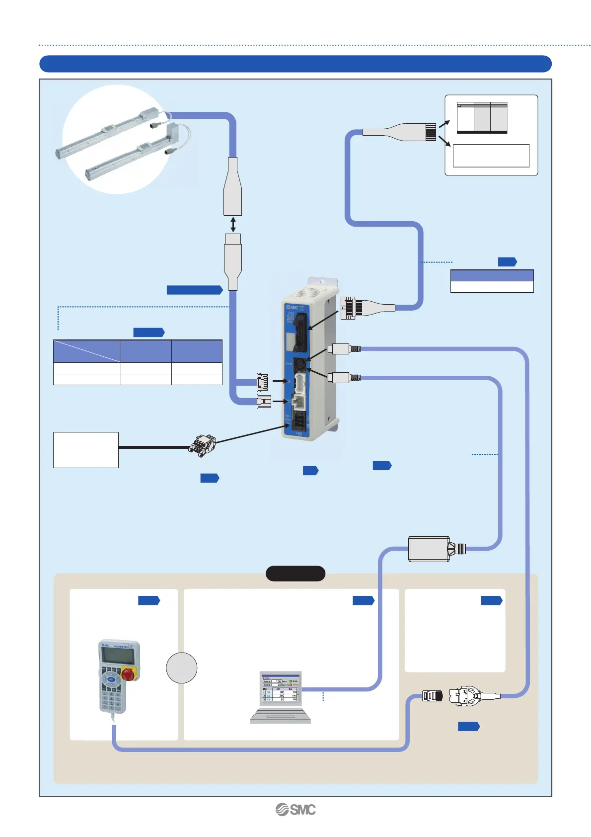
System Construction/General Purpose I/O
Electric actuator/
Slider type
PLC
Controller
∗
1
To SI
To SI
To ENC
To MOT
∗1 Can be included as an option. Refer to the “How
to Order” page of the actuator.
Actuator cable
∗
1
Power supply for I/O signal
24 VDC
To the parallel I/O connector
I/O cable
Provided by the customer
Step data input type
JXC51/61
Part no.
LEC-CN5-
Compatible encoder
Cable type
Incremental
Battery-less
absolute
Standard cable
LE-CP--S
—
Robotic cable
LE-CP- LE-CE-
Communication cable
(3 m)
To PWR
Power supply
plug
(Accessory)
Power supply
for controller
24 VDC
Provided by the customer
p. 16
p. 16
p. 8
p. 16
Web Catalogue
p. 14, 15
Teaching box
(With 3 m cable)
LEC-T1-3G
Options
USB cable
(A-mini B type)
(0.8 m)
PC
Communication cable for controller setting
Conversion cable
∗
2
P5062-5
(0.3 m)
Communication cable : JXC-W2A-C
USB cable : LEC-W2-U
<Controller setting software/USB driver>
· Controller setting software
· USB driver (For JXC-W2A-C)
∗ Download from SMC’s website:
https://www.smc.eu
The conversion cable can
be used for connecting this
controller to the optional
teaching box [LEC-T 1 ]
offered with the LEC series.
∗2 A conversion cable is also required to connect the JXC1 series controller and the LEC series communication cable (LEC-W2A-C).
(A conversion cable is not required for the JXC-W2A-C.)
Conversion cable
or
p. 16 p. 16 p. 16
p. 16
5
Step Motor Controller JXC Series
 Loading...


