- 20 -
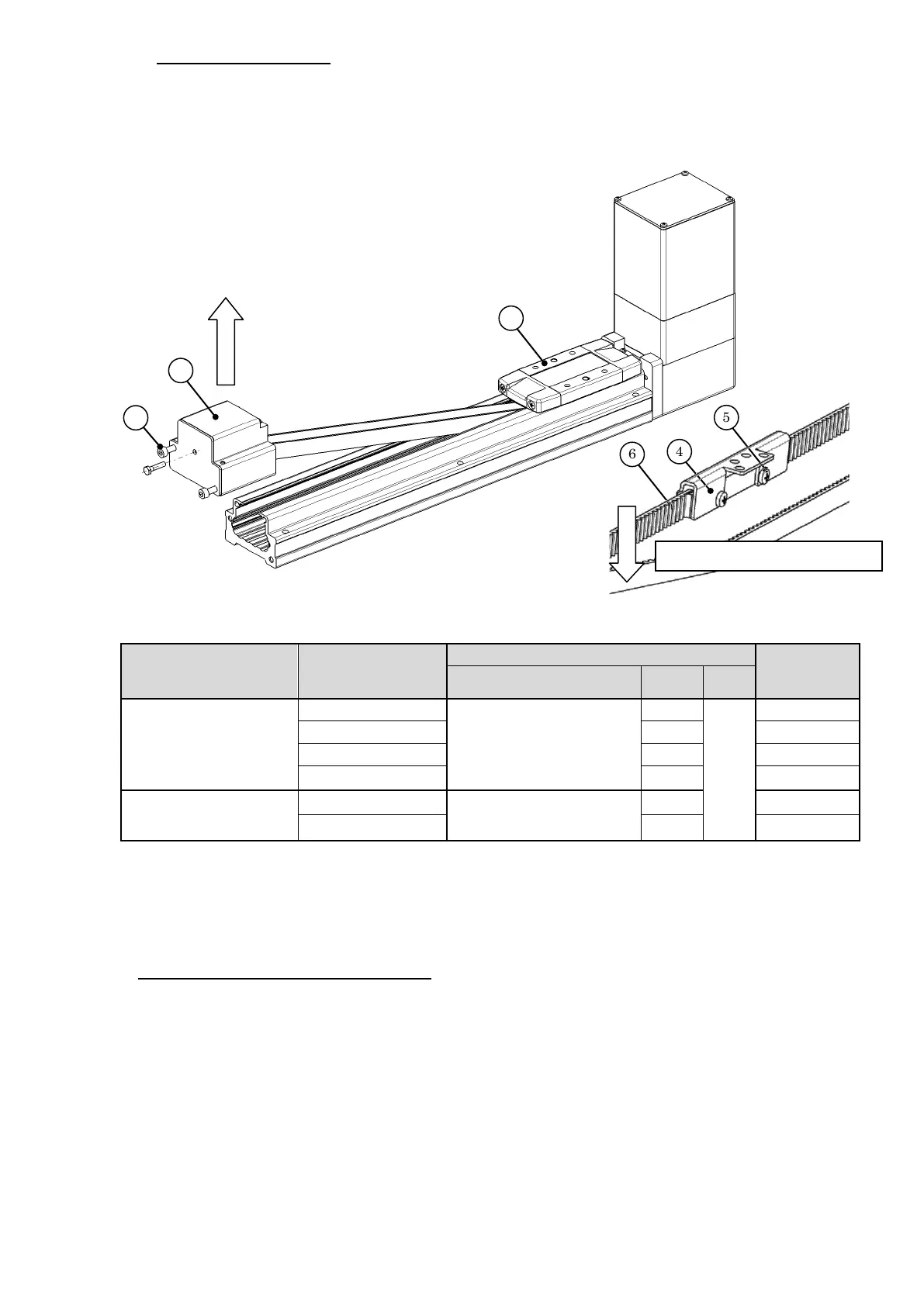
LEFB32, 40∗(S/T/V)∗S
Pull out the belt holder assembly (4) from the table (3). After loosening the hexagon
socket head cap screw (7), remove the end block assembly (8) from the body in the
direction of the arrow. Remove 2 cross recessed round head screws (5) to pull out
the belt (6) downward.
8-3. Pull the belt and remove it from the actuator.
8-4. To refit, mount the belt in reversed order of 8-1 to 8-3. Points to be Noted for Assembly.
Cautions 1):
LEFB16, 25, 32
∗T, LEFB25∗(S/T/V)∗S
Pass the belt to be replaced through the pulley holder assembly (9) in the reverse
order to the removal procedure (Fig.8-1) and securely install the belt into the table.
Then bring the end of the belt to the other end of the table. Confirm that the bearing
(10) is inserted into the housing on the motor side.
* To change the stopper position, mark the position before the change.
Part to be tightened Models
torque +/-
Type Size Qty.
(6) Belt
(5) Cross recessed round
head screw
2
(8) End block assembly
∗
(7) Hexagon socket head
cap screw
∗
M6x75 5.2
Table.8-2 Fixing screws of the belt and end block
Pull the belt in this direction.

 Loading...