Mx37y_Technical_Description_ENG_v2.00.doc
12
─ Single- and three-phase electronic meters with built-in DLC
modem, GSM/GPRS modem or RS485 comm. interface
The meter cover is made of transparent
polycarbonate. A nickel-plated iron ring in the right
top corner is utilized for attaching an optical probe to
the optical port. There is a lid which is fixed to the
meter cover with a hinge. The lid covers the Reset
push-button and can be sealed in the closed position.
A terminal block complies with the DIN 43857
standard. It is made of high quality polycarbonate
assuring resistance to high temperatures, voltage-
breakdown and mechanical strength.
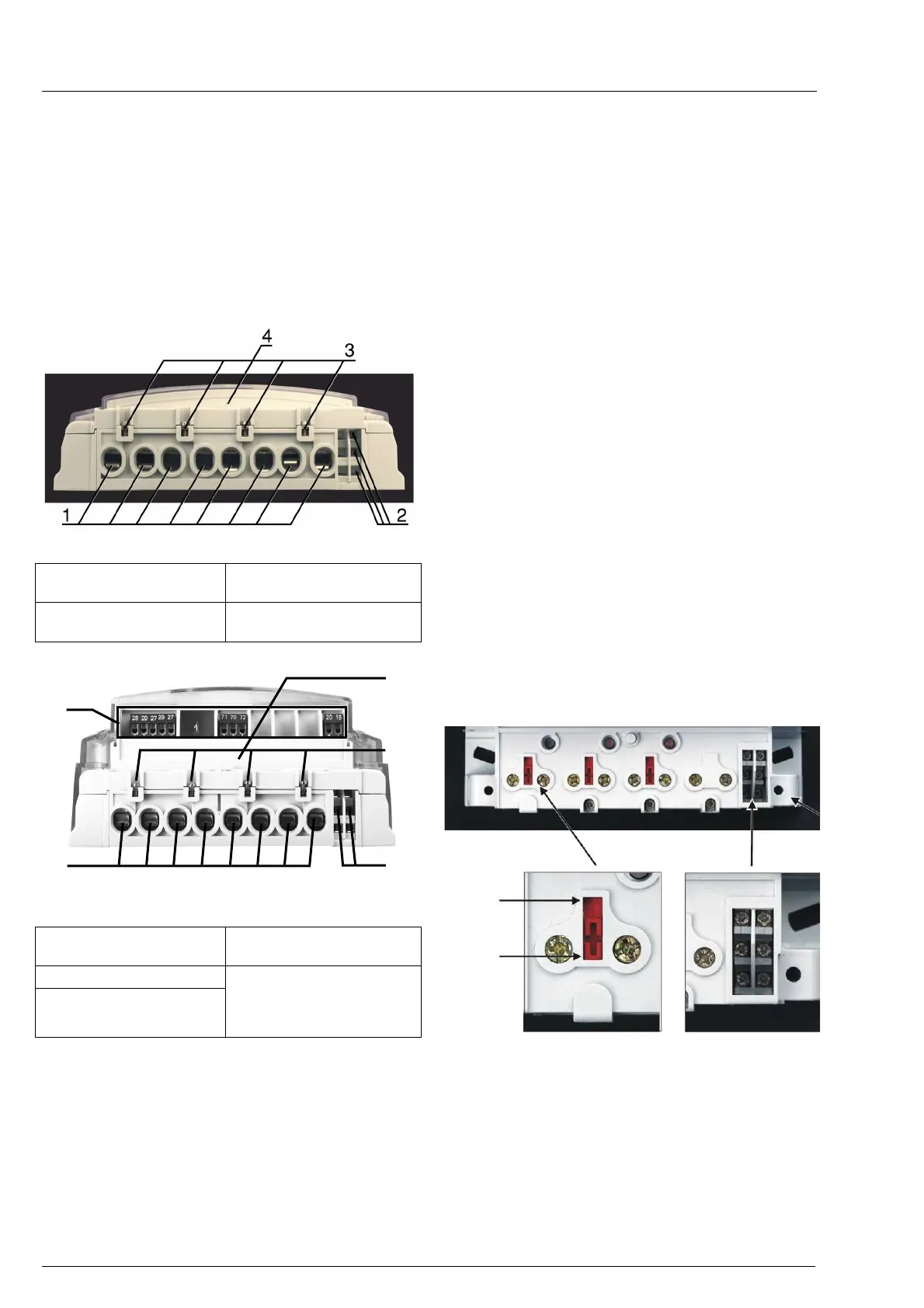
Fig. 10: A terminal block of MT371 meter – bottom view
1. Current terminals
3. Voltage terminals for an
add-on unit
2. Auxiliary terminals
4. Detector of opening a
terminal cover
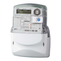
Fig. 11: A terminal block of MT372 meter – bottom view
1.
Current terminals
4. Detector of opening a
terminal cover
2. Auxiliary terminals
3. Additional voltage
terminals
5. Auxiliary terminals –
inputs, outputs, SIM
card bed, alarm
inputs, etc.
Current terminals (item 1) are made of zinc-plated
iron and have only one screw. A universal clamping
terminal assures the same quality of the contact
irrespective of the shape of the connection conductor
(a compact wire, a stranded wire, greater or smaller
cross-sections). It also assures faster meter
assembly. Available current terminals are:
• Current terminal according to DIN standard for
currents up to 85 A with 8.5 mm hole diameter
• Current terminal for currents up to 120 A with
9.5 mm hole diameter
• Current terminal for CT meters for currents up
to 6 A with 5.5 mm hole diameter
The meter can be equipped with max. four additional
voltage terminals (item 3): 2 (L1), 5 (L2), 8 (L3), 11
(N). They enable simple connection of additional
external devices.
Up to 6 auxiliary terminals (item 2) can be fitted in the
right side of the current terminals. They can be
utilized for M-Bus and optomos relay impulse output
or optomos relay control output. Instead of the
optomos relay a 6 A bistable relay for load control
can be built into the meter. All of them are fitted into
the meter regarding the customer request at meter
ordering.
Versions:
-
two pulse outputs (A+, R+) and relay (6 A) +
optomos (100 mA)
- M-Bus and relay (6 A) + optomos (100 mA)
Detectors (switches) of the terminal cover (item 4)
and the meter cover opening (on the PCB next to the
optical port) are built into the meter.
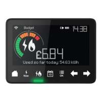
A sliding voltage bridge is intended for fast and
simple separation of meter current and voltage circuit
used for calibration or accuracy testing. A special
slider is built in each phase of the connection
terminal. It can be shifted up and down with a
screwdriver.
Sliding voltage bridge Auxiliary terminals
Fig. 12a: A terminal block – sliding voltage bridge and
auxiliary terminals
Whe
n a voltage bridge is in “0” position, it means that
the voltage part is separated from the current part.
During the meter testing and calibration the sliding
voltage bridges should be in position “0”.
Position 0
Position 1
4