Mx37y_Technical_Description_ENG_v2.00.doc
13
─ Single- and three-phase electronic meters with built-in DLC
modem, GSM/GPRS modem or RS485 comm. interface
When a voltage bridge is in position “1”, the voltage
part is not separated from the current part. During the
normal meter operation the potential links should be
closed (position “1”). Upon request, the potential links
can be built under the meter cover.
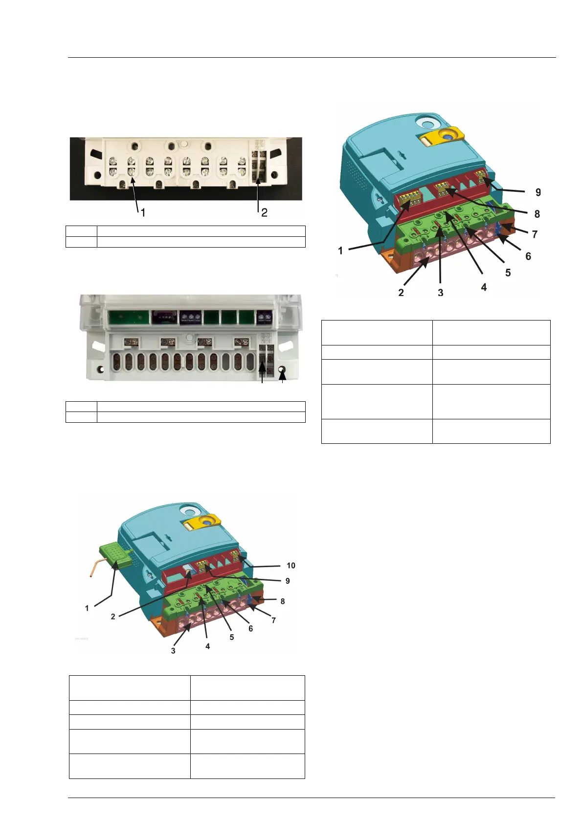
1 Double cage clamp
2 Auxiliary terminals
Fig. 12b: A terminal block with auxiliary terminals
MT37y : 3x230/400 V, 10(120) A
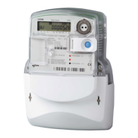
1 Auxiliary terminals
2 Terminal cover sealing screw
Fig. 12c: A terminal block with auxiliary terminals
MT37y CT : 3x230/400 V, 5(6) A
The terminal cover can be long or short. The meter
c
onnection diagram is stuck on the internal side of
the terminal cover.
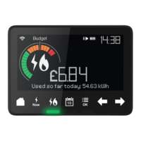
Fig. 13: Details of a terminal block for GSM/GPRS meter
1. Coupling circuit for
external antenna
6. Additional voltage
terminals
2. SIM card bed 7. Outputs for load control
3. Current terminals 8. M-Bus
4. A sliding voltage bridge
9. Output for switching
device control
5. A switch for detection of
terminal cover opening
10. Alarm input (low
voltage)
Fig. 14: Details of a terminal block for RS485 meter
1. RS485 comm.
interface
6. Outputs for load control
2. Current terminals 7. M-Bus
3. Sliding voltage bridge
8. Output for switching
device control
4. A switch for detection
of terminal cover
opening
9. Alarm input (low voltage)
5. Additional voltage
terminals