EN – 32
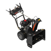
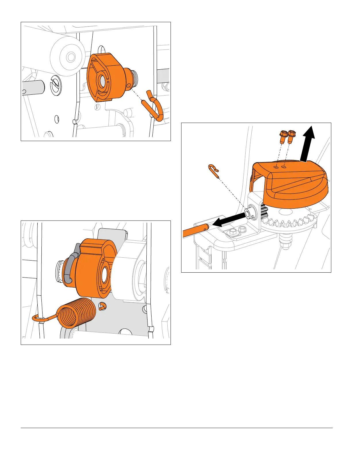
3. Position left interlock cam inside interlock bracket and
align with left camshaft.
4. Insert camshaft through cam.
5. Secure camshaft to clutch lever with one tapping
screw.
See Figure 69.
6. Rotate cam so flat edge is positioned upward and
secure with spring clip.
7. Reconnect spring to interlock bracket.
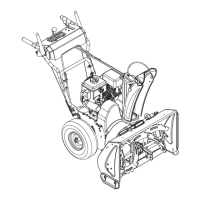
CHUTE GEAR REPLACEMENT
Remove Pinion Gear
IMPORTANT: Save all hardware for reinstallation unless
specified otherwise.
1. Stop engine, remove key and wait for all moving parts
to stop and for hot parts to cool.
2. Disconnect spark plug wire from engine.
See Figure 70.
3. Remove hardware retaining chute gear cover to chute
pedestal and remove cover.
4. Remove spring clip from chute rotation rod and
remove rod from chute gears.