Components/Connections
15
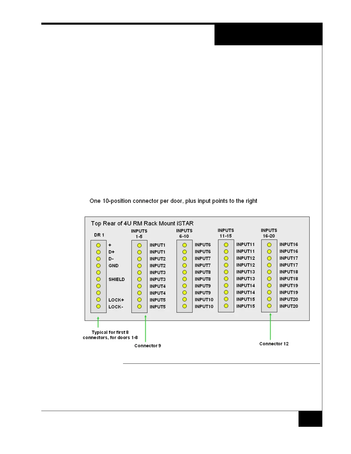
Top Row Rear Connectors
Figure 6 and Figure 7 show details of the rear connectors.
The door connectors provide +12 VDC, Data+, Data-, and GND for the RM-4 or
RM-4E. Doors 1-8 are mapped to doors 1-8 of the first ACM. Doors 9-16 are
mapped to doors 1-8 of the second ACM.
The Lock outputs can be sourced with 24VDC or 12VDC for lock power or other
output devices. The Lock outputs can also be set as Dry Contacts and used with
external power for the locks or can be used as ordinary outputs. There is also a
grounded pin to connect the shield of the cables.
The inputs are ordinary Software House supervised inputs that can be wired as
NO or NC. Each pair is wired to an input on the ACMs. Inputs 1-16 are mapped
to inputs 1-16 of the first ACM. Inputs 17-32 are mapped to inputs 1-16 of the
second ACM.
FIGURE 6. Top Row Rear Connectors - 4U RM Rack Mount ISTAR