Components/Connections
16
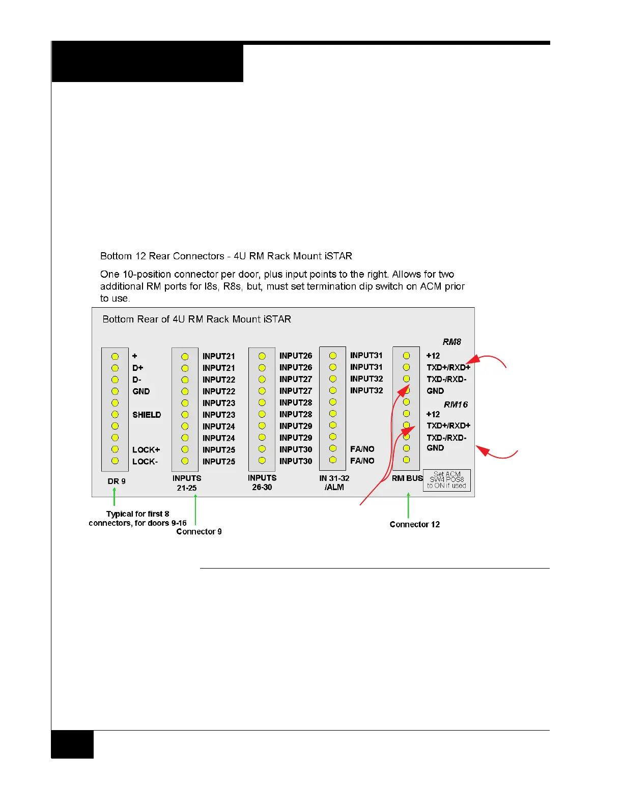
Bottom Row Rear Connectors
Doors 9-16 and Inputs 21-32 are on the bottom connector.
The Fire Alarm input (FA/NO) on the IN31-32 connector is a Normally Open
(NO) dry connection. When the connection closes, it indicates an external Fire
Alarm is active. If an APD8 jumper is set to position D, the lock power for that
lock will be inhibited. See Figure 20 for more details. The Fire Alarm will also be
indicated on the front panel and can be wired to an input and used to create an
event in the C•CURE system. See page13.
FIGURE 7. Bottom Row Rear Connectors - 4U RM Rack Mount ISTAR
Adding I/8 or R/8 Bus Modules
It is possible to wire bus modules on the same lines as Doors 1-16, observing
normal RS-485 termination rules.
Another option is to use the RM BUS connector. The RM BUS connector has two
RM Bus connections which can be used to wire I/8 and R/8 bus modules.
RM 8 and DR 8 are connected to STAR1 on the first ACM. RM 16 and DR 16 are
connected to STAR1 on the second ACM.
Tied to Door 8
on ACM 1
Tied to Door 16
on ACM 2
Set ACM S1-1 to OFF
when RM8/16 are used