Components/Connections
26
Interconnections
Lock Varieties
RM4 to Head End Wiring Instructions
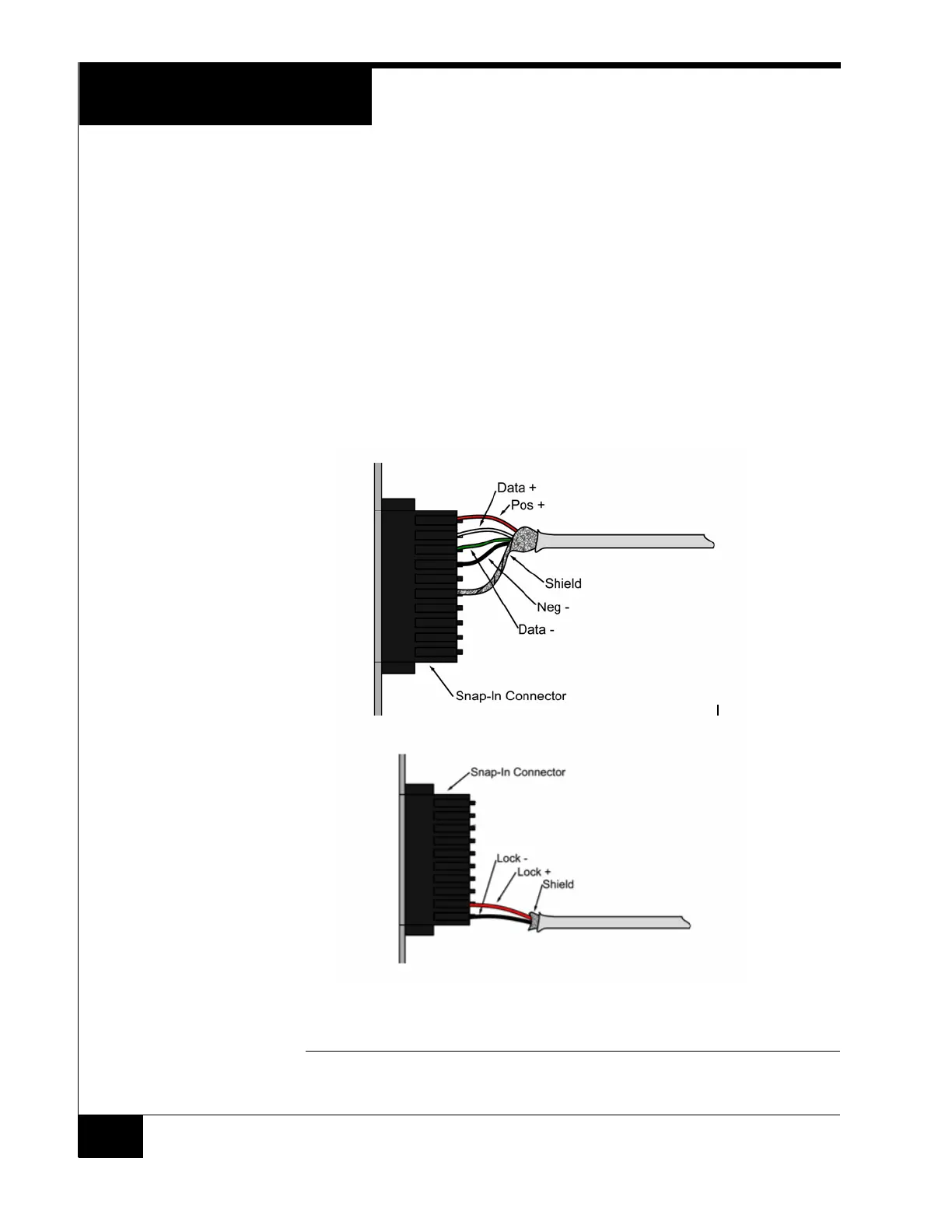
Reader Diagram
1. Connect RM Power (Red) to pin 1
2. Connect Data + (White) to pin 2
3. Connect Data - (Green) to pin 3
4. Connect RM GND (Black) to pin 4
5. Connect the shield to pin 6
Figure 18 shows the wiring connections for an RM reader connector.
FIGURE 18. RM Door Snap-In Connector