April 21, 2021 5
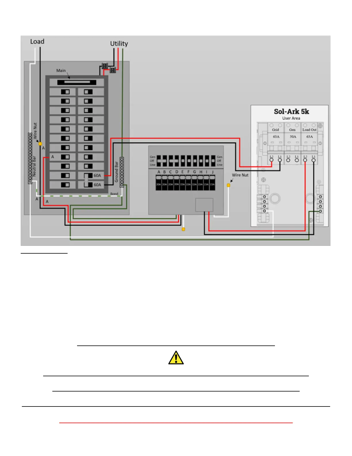
5. Mount Multi-Circuit Transfer Switch (Not valid for Arc-Fault/GFI breakers) OR Backup Loads Panel
Important notes:
When the transfer switch is in the “Gen” position, this means the circuit is being powered by the Sol-Ark
(which can use Grid/Solar/Battery/Generator automatically).
When in the “Line” position, the transfer switch is being powered by the grid (Sol-Ark can be removed).
The transfer switch setup is complete once all the switches are set to “Gen” position.
The Sol-Ark will take care of the rest.
If you are not installing a transfer switch (Off Grid or have a 50A sub-load panel), you can wire the “Load”
output of the Sol-Ark 5K directly to a Main Lug breakers sub-panel rated for at least 50A.
Please refer to diagrams section for complete wire diagram
Strain Reliefs must be used for all wires going in/out of the Sol-Ark 5K user area
Ground and Neutral must be wired as shown above, or damage can occur.
Conduit (or double insulated wire) must be used for the AC Wires going to and from the Sol-Ark.
DO NOT CONNECT THE GRID TO THE LOAD OUTPUT BREAKER
Step 1. Turn off main breaker
Step 2. Connect White/Neutral wire (4 AWG) to Neutral Bar
Step 3. Connect Green/Ground wire (6 AWG) to Ground Bar
Step 4. Remove load wire (12 AWG) from circuit breaker and connect
it to the black “A” wire (12 AWG) with a wire nut.
Step 5. Place red “A” wire (12 AWG) from the switch into breaker.
Step 6. Repeat steps 4-5 for circuits A-J
Note: All AC wires should be 4 AWG