6
3 Description
All SolarMax inverters work completely automatically. The DC circuit breaker is
always on during normal operation. The inverter starts when there is enough input power
and continues to operate until the available input power from the PV generator drops
below the necessary minimum.
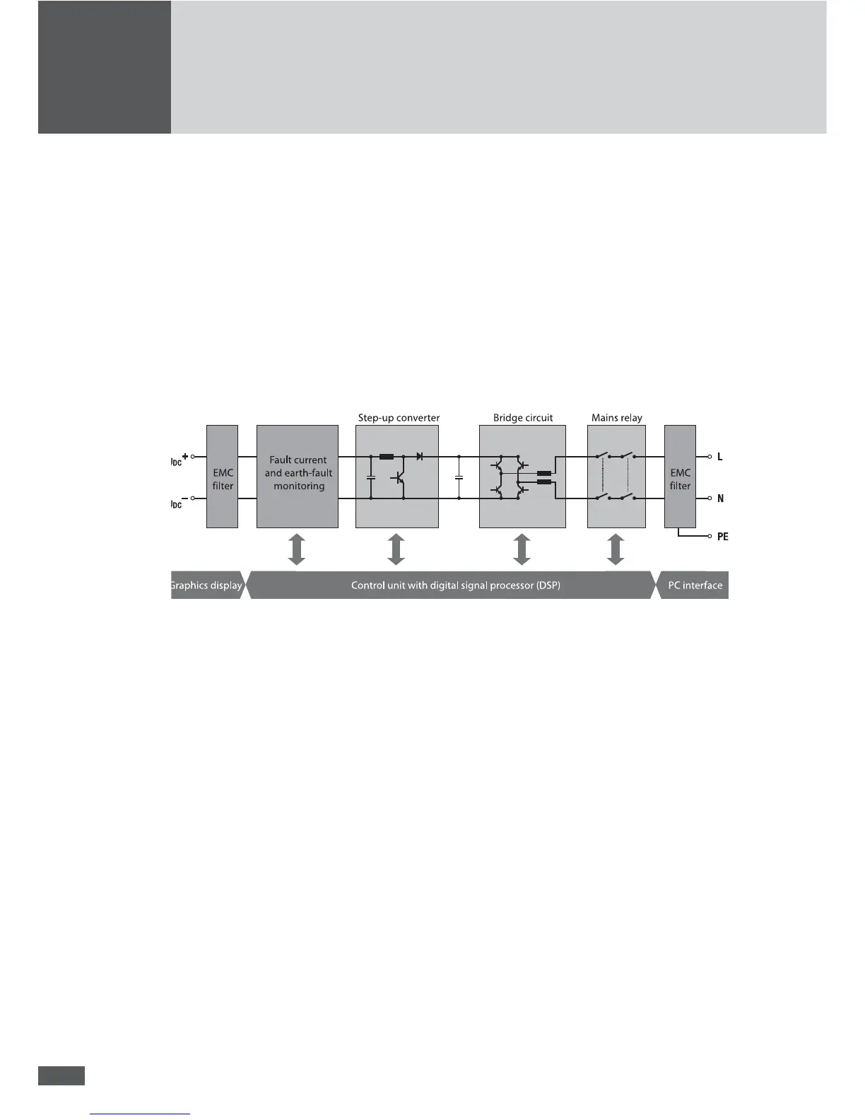
3.1 Technical con guration SolarMax 2000S/3000S
The DC voltage of the PV generator is transferred to a DC bus voltage via a low-loss step-
up converter. The IGBT bridge circuit generates the sinusoidal infeed current.
3.2 Technical con guration SolarMax 4200S and
SolarMax 6000S
The DC voltage of the PV generator is transferred to a DC bus voltage via a low-loss step-
up converter. The IGBT bridge circuit generates the sinusoidal infeed current.
The innovative MaxShare concept leads to a tangible boost in ef ciency during periods
of partial load. MaxShare switches the required power stages on or off according to the
current output.