Operation MethodOperation Method
Grid Protection
f ) New Password
The user can set the new password here. We need to increase or decrease the
word by pressing “Up” or “Down” button. Long press “Down” to confirm and
alternate to next word. After word is confirmed, long press “Down” to reset the
password.
> O/V Stage1
0.0
New Password
1 2 3 4
g) RS485 CommAddr
If “ nable” is selected, the inverter will communicate with the computer, E
through which the operating status of the inverter can be monitored. When
multiple inverters are monitored by one computer, RS485 communication
addresses of different inverters need to be set. The default address is “1”.
RS485 CommAddr
Set Address
1
e) Grid Protection
Usually end user do not need to set the grid Protection. All default value have
been set before leaving factory according to safety rules.
If reset is needed, any changes should be made according to the requirements of
local grid.
h) ParallelSetting
Make sure this setting is disabled (by default) all the time. (The series inverter
does not support parallel connection without Datahub).
Mode Select
Disable
ParallelSetting
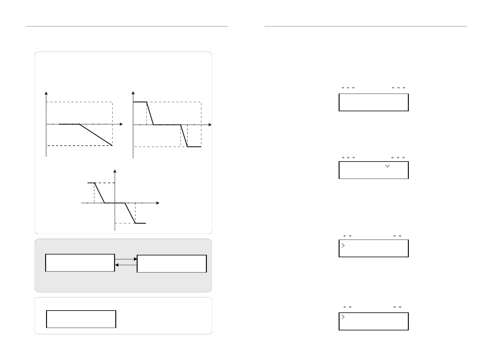
Reactive power control, Reactive standard curve cos φ = f(P)
For VDE ARN 4105, curve cos φ = f(P) should refer to curve A. Default values of setting are
as shown in curve A.
For E 8001, curve cos φ = f(P) should refer to curve B. Default values of setting are as
shown in curve B.
Reactive power control, Reactive standard curve Q= f(V)
Q
V
Qmax
-Qmax
V2sV1s
V1iV2i
V2i=0.90Vn
V2s=1.10Vn
V1s=1.08Vn=QuVlowRate
V2i=0.92Vn=QuVlowRate
0.9
0.9
Upper limit
capactive
inductive
f (P)
Lower limit
Power Lower
Power Upper
curve B
0.3
0.7
0.2
0.8
4-2.
5.
Power Limits
0.40
User can set the power limit
here, the setting value is
between 0.00 and 1.00.
6.
P(u) Function
>Enable<
> Proportion
Enter
Back
This function can limit the power. There are several values to be set.
﹦ ﹦ ﹦ ﹦ ﹦ ﹦
﹦ ﹦ ﹦ ﹦ ﹦ ﹦ ﹦ ﹦
0.9
0.9
Upper limit
f (P)
Lower limit
curve A
0.2
0.5
> Enable/Disable
> Vw1
242
48 49

 Loading...


