Ø Parallel system with Datahub
In this parallel system, at most 60 inverters can be connected. The Datahub will
be the master of the system, and all the inverters are the slaves. The Datahub
can communicate with all the slave inverters.
a) Connect on end of an RS485 communication cable with Datahub, and the
other end with one of the slave inverters.
b) Connect all the slave inverters with each other via RS485 cables.
c) Connect the meter with the Datahub and the mains.
Ÿ Wiring operation
Note!
The inverter connected with the Datahub should not enable
the “ParallelSetting”.
There is no need to set the “ParallelSetting” on the inverters,
the parallel system with Datahub will start automatically.
For the details, please refer to the user manual of Datahub.
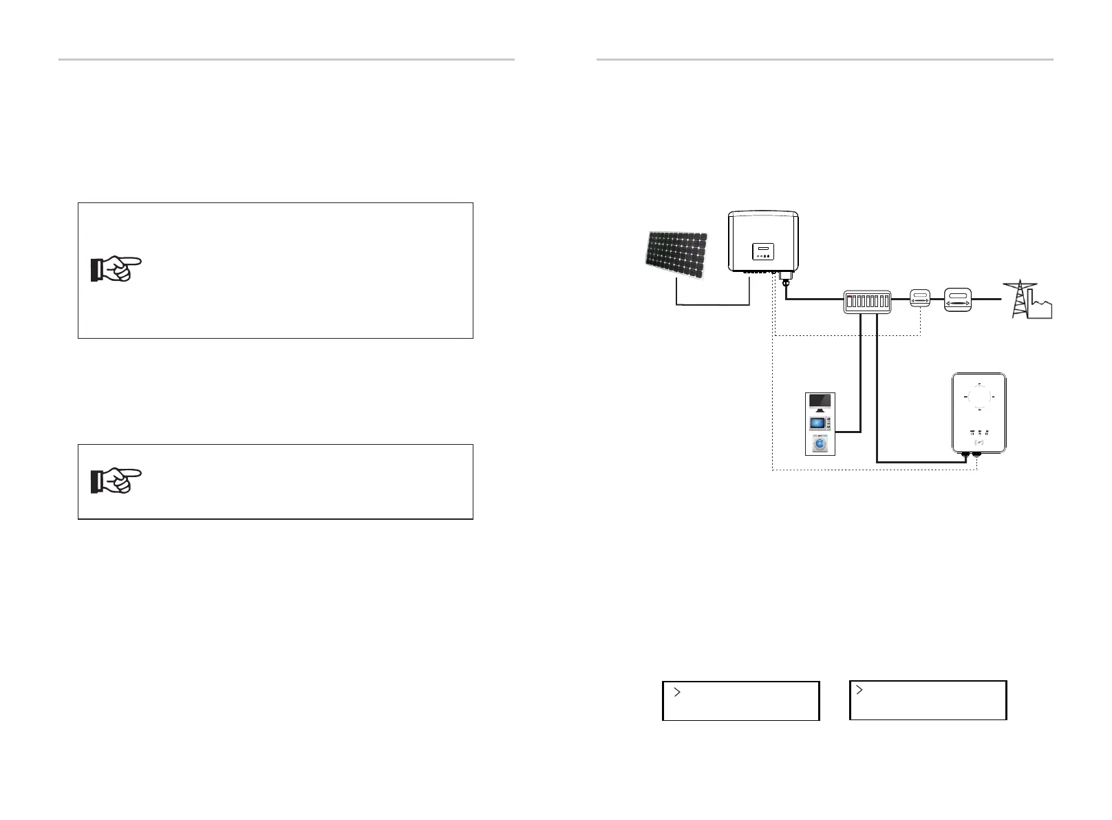
6.4.3.3 EV-Charger Function
The inverter can communicate with the smart EV-Charger to form an
intelligent photovoltaic, storage and EV charging energy system, thus
maximizing the utilization of photovoltaic energy.
Electrical
grid
PV array
AC distribution box
Inverter
Electricity meter,
bidirectional
Meter
a) Plug one end of the communication cable to the right pin of the EV-Charger
and the other end to PIN 1 & 2 or 3 & 4 of the "RS485" port of the series inverter.
b) Connect the meter to PIN 5 & 6 of the "RS485" port of the inverter.
Ÿ Wiring operation
Turn on the power of the entire system, enter the “Settings” page of the
inverters on the LCD screen.
a) Enter the “Export Control” page and choose “Meter”.
Ÿ LCD setting
Mode Select
Meter
Export Control
DRM Function
Diagram: Intelligent Photovoltaic, Storage and EV Charging Energy System
46 47
Electrical Connections Electrical Connections
Note!
Before connecting the Datahub to the parallel system, please
check that the inverters' settings meet the following
conditions:
1. The “Modbus Fuction” should be “COM485”.
2. The “ParallelSetting” should be “Disable”.
3. The addresses of all the inverters in the “RS485 CommAddr”
should be different. Otherwise, please reset the RS485
communication addresses.
Loads
EV-Charger

 Loading...