6 Electrical Connections
6.1 PV Connection
The series inverter have three couples of PV connectors which can be connected
in series into at most 3-inputs of PV modules. Please select photovoltaic modules
with good performance and quality assurance. The open circuit voltage of the
module array should be less than the maximum PV input voltage specified by the
inverter, and the operating voltage should be within the MPPT voltage range.
Table: Max. DC Voltage Limitation
Max. DC Voltage
1100 V
Warning!
The voltage of PV modules is very high and dangerous , please
comply with the electric safety rules when connecting.
Warning!
Do not ground the positive or negative pole of the
photovoltaic module!
Note!
Please follow the requirements of PV modules as below:
Same type; Same quantity; Identical alignment; Identical tilt.
In order to save cable and reduce the DC loss, we suggest
installing the inverter near PV modules.
Electrical Connections Electrical Connections
Model
Danger!
Danger to life due to high voltage on DC conductors.
when exposed to sunlight, the PV array generates dangerous DC
voltage which is present in the DC conductors. Touching the DC
conductors can lead to lethal electric shocks.
Do not cover the PV modules. Do not touch the DC conductors.
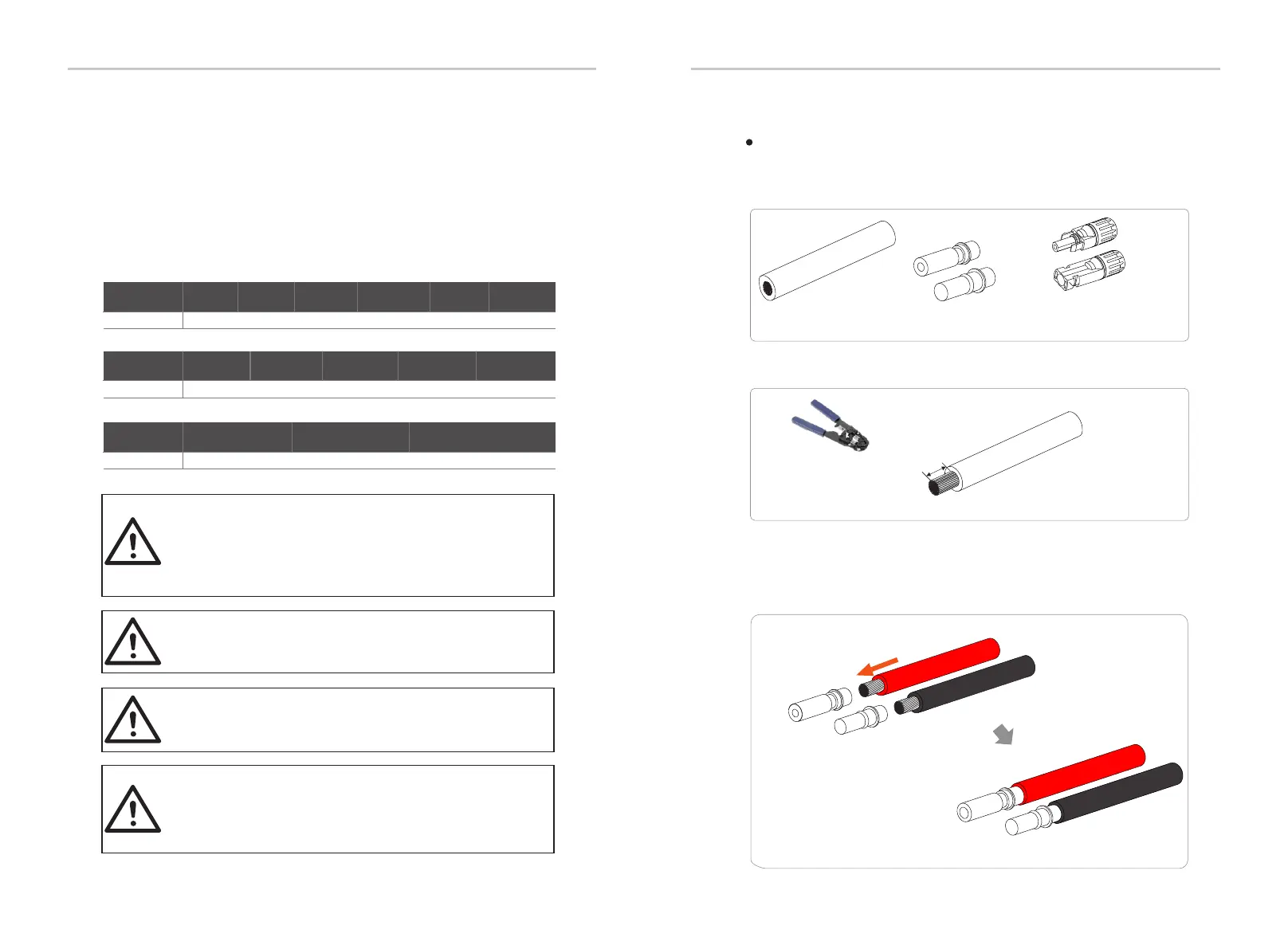
Connection Steps
X3-PRO-8K-G2(2D) X3-PRO-10K-G2(2D) X3-PRO-15K-G2 (2D) X3-PRO-12K-G2(2D)
Step 1. Turn off the DC switch, connect the PV module, prepare a 4 mm PV
cable, and find the PV (+) terminals and PV (-) terminals in the package.
PV cable
PV pin contacts
Negative terminals
Positive terminals
Step 2. Use a wire stripper to strip 7 mm insulation layer from the wire end.
7.0 mm
Wire stripper
Step 3. Tighten the cable with the insulation layer stripped and insert it into
the pin contact (see Figure 1), make sure all wires are inserted into the pin
contact (see Figure 2).
Figure 1
Figure 2
Positive PV
pin contact
Negative PV
pin contact
X3-PRO-17K-G2(2D) X3-PRO-20K-G2(2D)
Max. DC Voltage
1100 V
Model
X3-PRO-25K-G2(3D) X3-PRO-30K-G2(3D) X3-PRO-20K-G2(3D) X3-PRO-17K-G2(3D) X3-PRO-15K-G2 (3D)
Max. DC Voltage
800 V
Model
X3-PRO-10K-G2-LV X3-PRO-12K-G2-LV X3-PRO-15K-G2-LV
26 27
 Loading...


