Mains cable (AC line cable) shall be short-circuit protected and thermal
overload protected.
Always fit the input cable with fuse. Normal gG (US:CC or T) fuses will protect
the input cable in short circuit situation. They will also prevent damage to
adjoining equipment.
Dimension the fuses according to local safety regulations, appropriate input
voltage and the related current of the solar inverter.
The rated short-circuit breaking capacity of the above protective device shall
be at least equal to the prospective fault current at the point of installation.
See section technical data of this manual for details.
AC output cable: Cu; L1,L2,L3, N+ : 3*5.0 mm +2*5.0 mm for
2 2
PE X3-PRO-8K-G2
2 2
and 3*6.0 mm +2*6.0 mm for X3-PRO-10K-G2/X3-PRO-12K-G2/X3-PRO-15K-
2 2
G2 and 3*8.0 mm +2*8.0 mm for X3-PRO-17K-G2/X3-PRO-20K-G2/X3-PRO-
2 2
10K-G2-LV and 3*10.0 mm +2*10.0 mm for X3-PRO-25K-G2/X3-PRO-30K-
G2/X3-PRO-12K-G2-LV/X3-PRO-15K-G2-LV @40 ambient temperature.℃
Selection of Fuses and Cables
1. For condition differing from those mentioned above,
dimension the cables according to local safety regulations,
appropriate input voltage and the load current of the unit.
(You can choose a thicker cable but the fuses must be rated
according to the rating of the cable.)
2. Fuses must be approved by Notified Body.
Note!
Therefore the current-carrying capacity of the components and sub-
assemblies provided in the end-use system (connectors, cables, junction box,
switchgear, etc.) and the reverse current PV modules shall be considered
based on the feedback current and reverse current. The direct current (DC)
circuit breaker or fuse between each solar generator and inverter shall be
provided based on solar inverter input ratings.
Select DC cables based on the above inverter back-feed current and ISC PV
rating and Vmax ratings.
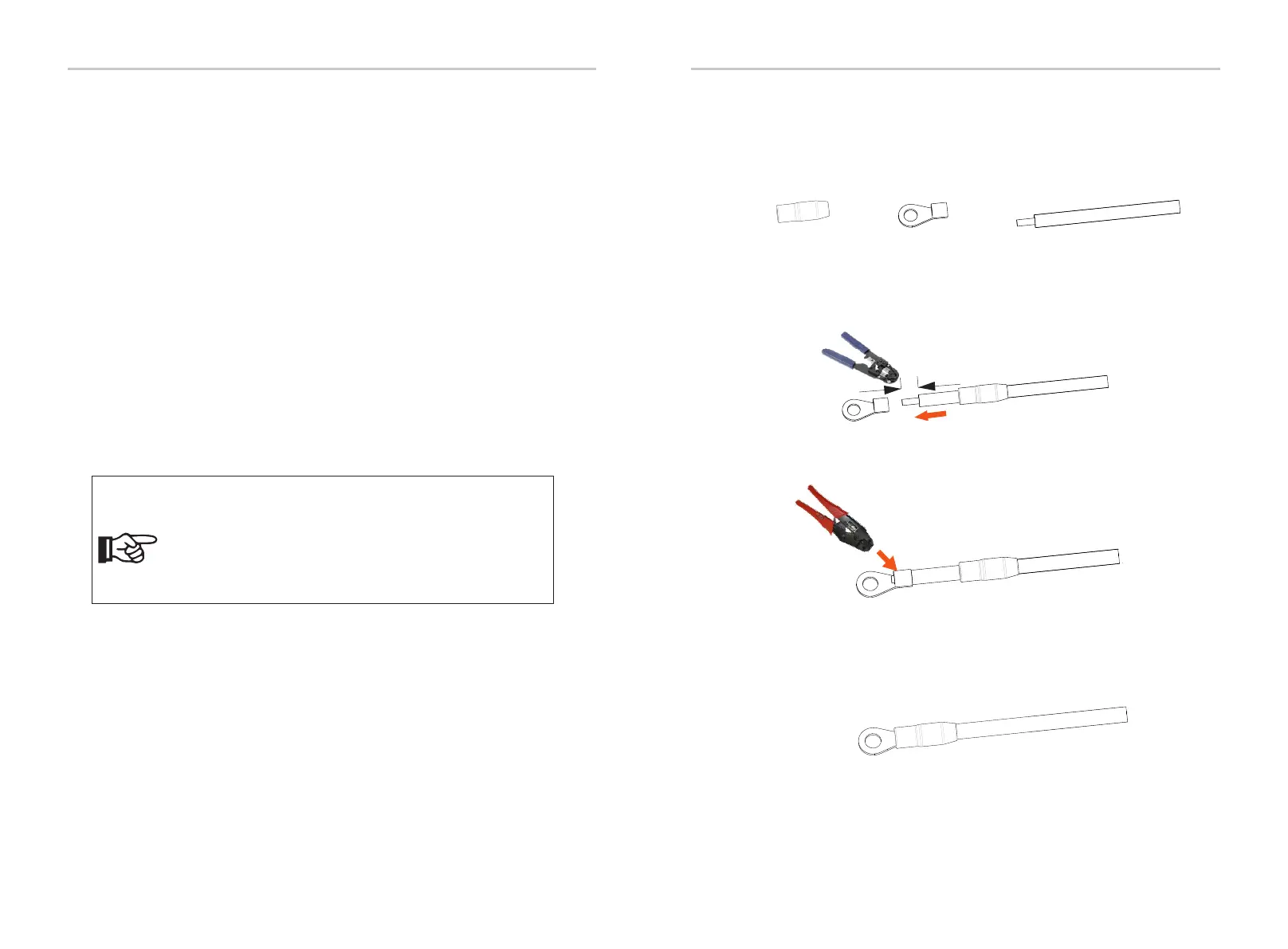
6.3 Earth Connection
a) Find the terminal sleeve and the R-type terminal in the accessories.
Prepare a grounding cable (4 mm).
terminal sleeve
R-type terminal
cable
b) Strip 7 mm insulation layer from the end and pull the terminal sleeve
over the cable.
c) Insert the stripped section into the R-type terminal and crimp it.
Crimping Tool
d) Pull the terminal sleeve over the crimped section of the R-type terminal
and make sure it is firmly contacted with the terminal.
Wire stripper
7 mm
34 35
Electrical Connections Electrical Connections

 Loading...