THERMOCUBE II 200-650W THERMOELECTRIC CHILLER MANUAL 52-14790-1
SOLID STATE COOLING SYSTEMS, 167 MYERS CORNERS ROAD, WAPPINGERS FALLS, NY 12590 23
TELEPHONE: (845) 296-1300, FAX: (845) 296-1303, WEB: WWW.SSCOOLING.COM VERSION M2
7.2.2 RS-232 HEX Command Communication Protocol
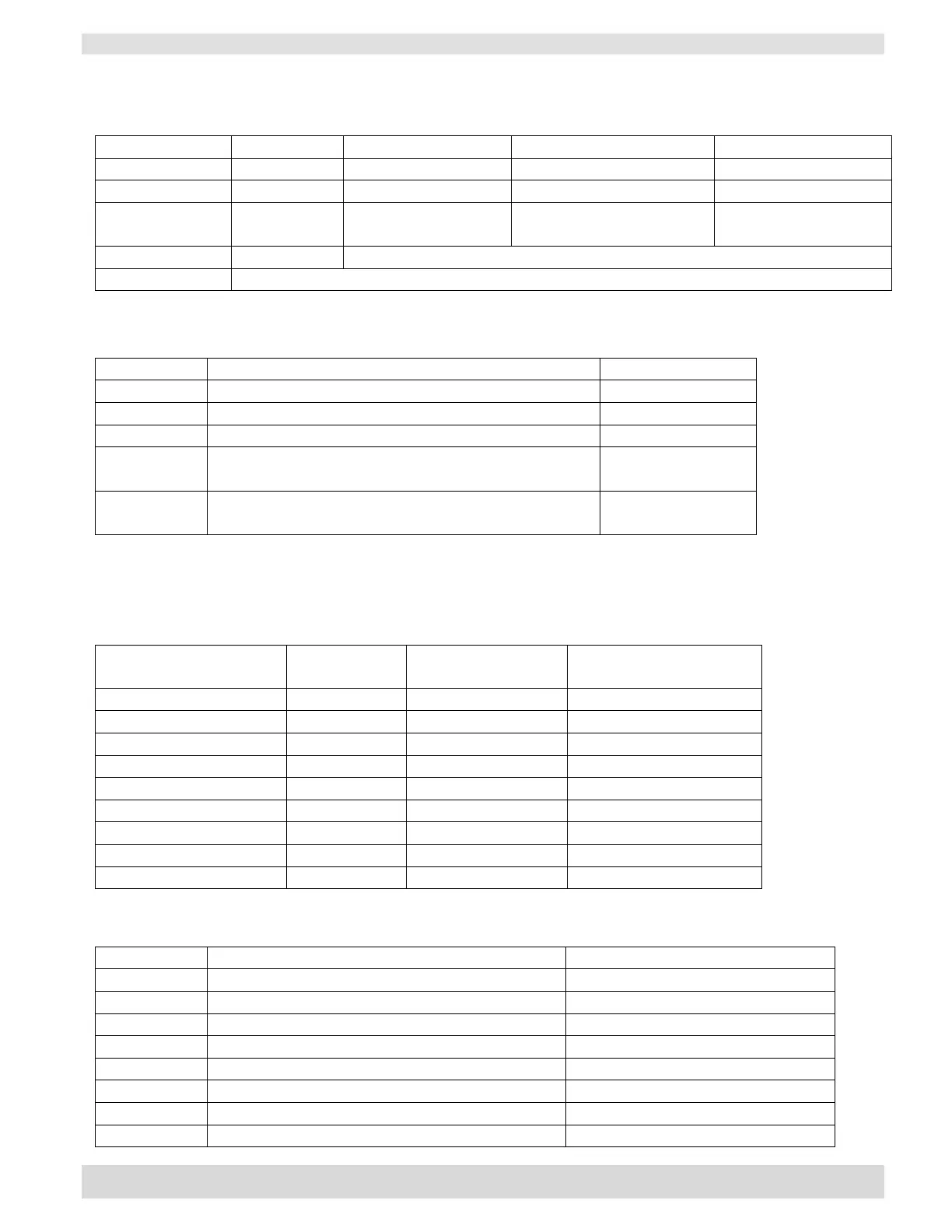
Table 2: Command and Data Bytes
remote to chiller
(command from master)
chiller to remote
(status from chiller)
Parameters being communicated (see table 2)
1 or 2 bytes depending on parameter (see tables 3-6)
Timing: ThermoCube II can accept a maximum of three commands per second
Table 3: Control Parameter
Chiller set point 1 temperature
Current fluid temperature at chiller coolant output
Faults from chiller (fan, pump, RTD failure, etc.)
% Cooling or Heating in Hex (Byte 1)
80 if Cooling and 00 if Heating (Byte 2)
Table 4: Temperature Data Bytes (2 bytes)
The 2 data bytes for the temperature set point and transmission of the current temperature represent the
value of the temperature in 0.1°F increments.
For example:
Table 5: Faults Data Byte (1 byte)
0 = OK, 1 = Fault
Hex value when fault is present
Flow Fault (Flowmeter Option Only)
Leak Detected (Leak Detect Option Only) _
Stop (chiller in standby)