ORIGIN User Guide
Origin Stereo Groups
19
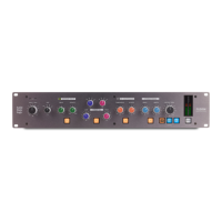
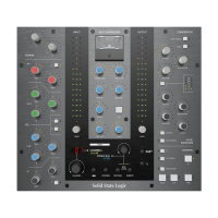
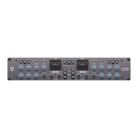
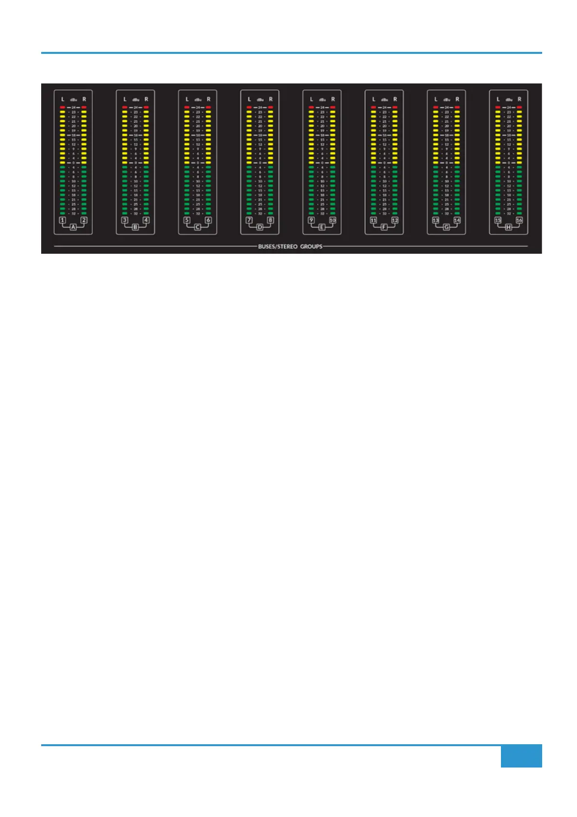
BUSES/STEREO GROUP METERS
Above the Centre Section are the eight stereo meters that show the levels coming into the Stereo Groups. As can be seen in the
block diagram on the previous page, the meters are fed after the input buffers and Mono switching, but before the Fader and
Balance controls. As the 'normal' wiring into the Stereo Groups is likely to be from the sixteen Track Buses, the meter labelling
shows this relationship with a combination of numbers with paired connections to the letters A-H representing the eight Stereo
Groups.
As with the channel metering, the meters are calibrated in dBu and they are peak meters with dened lines for +24 dBu and +18
dBu as well as 0 dBu. The meter has a fast ‘peak’ response and a slower release time to meter peaks while still showing useful
signal levels.
MONO L and MONO R
After the input buffers into the Stereo Groups there is Mono switching which allows a Mono signal to be split to both left and right
channels through the Stereo Group. The MONO L switch takes the left signal and sends it to left and right channels, the MONO R
switch takes the right signal and sends it to left and right channels. If both MONO L and MONO R switches are pressed, both left
and right paths are summed in mono through the Stereo Group.
BALANCE
The BALANCE control adjusts the balance of the left and right signals from the Stereo Group.
0dB
The 0dB switch bypasses the stereo group fader to give a xed unity gain through the Stereo Group signal path.
SOLO and CUT
The SOLO switch activates the Solo function for the Stereo Group Fader. The function of the SOLO switch is controlled by the
SOLO MASTER section in the centre section. Typically the SOLO switch is an After Fader Listen (AFL) function. This can be
switched to destructive Solo In Place using the SUBGROUP SIP switch in the SOLO MASTER section.
See the SOLO MASTER section on page 30 for more details on the Solo options.