ORIGIN User Guide
Detailed Channel Description
8
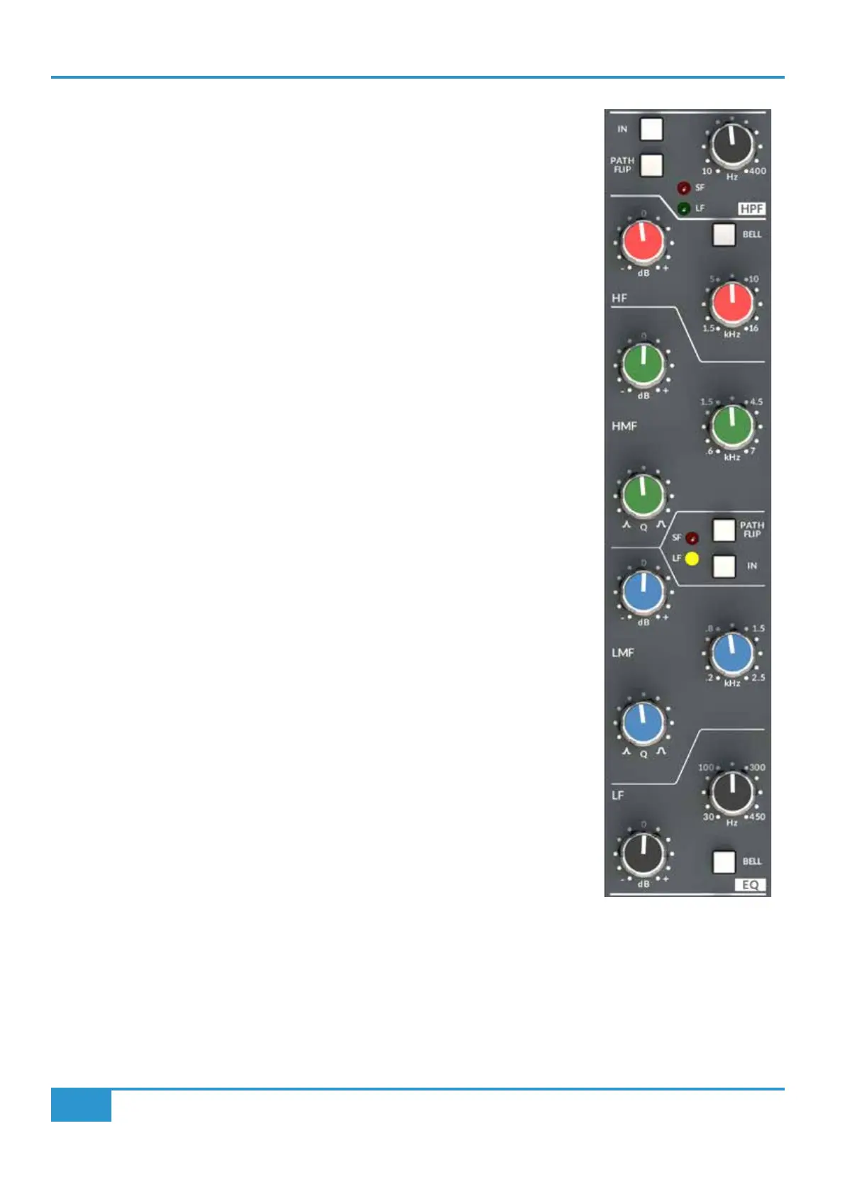
Parametric EQ and High Pass Filter (HPF)
At the top of the ORIGIN EQ section is the High Pass Filter (HPF) section. This has a 18 dB/
Octave slope and has a variable corner frequency from 10 Hz to 400 Hz. As can be seen in the
block diagram on the next page, the HPF actually follows the EQ section in the default signal
ow, however the HPF has an independant IN switch and also a PATH FLIP switch allowing it to
be separately positioned in the Small Fader (SF) or Large Fader (LF) paths.
The Parametric Equaliser in ORIGIN is based on the original SL4000E Series "242" equaliser
design i.e. SSL’s classic 'Black Knob' EQ.
The individual bands function as follows:
HF high frequency 12 dB/Octave shelving equaliser switchable to xed Q parametric (BELL).
HMF high frequency parametric mid band equaliser with continuously variable Q control.
LMF low frequency parametric mid band equaliser with continuously variable Q control.
LF low frequency 12 dB/Octave shelving equaliser switchable to xed Q parametric (BELL).
The EQ IN switch (located next to the insert switches) routes the channel signal through the EQ
section. The PATH FLIP switch allows the EQ to be separately positioned in the Small Fader (SF)
or Large Fader (LF) paths.