ORIGIN User Guide
Detailed Channel Description
5
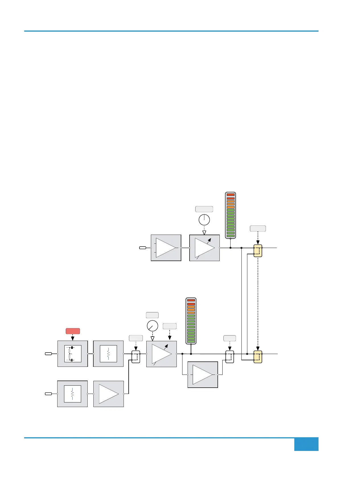
MON (Monitor) Input
The line level Monitor input is via a DB-25 connector (Mon Line In) also mounted on the rear of the console. Typically these inputs
will be wired to a patchbay (see Appendix F). Nominally this input is at unity gain, with a +20 db to -20 dB gain TRIM adjustment
to compensate for lower or higher Line level signals.
PATH FLIP
By default, the CHAN input feeds the Small Fader (SF) path and the MON input feeds the Large Fader (LF) path. This is indicated
by the red and green LEDs that bridge the line between these two sets of input controls. This default routing can be swapped by
using the PATH FLIP switch. When this switch is pressed, the red and green LEDs also ip status to show the path routing of the
input sections. This philosophy is repeated through the channel strip sections i.e.
RED LED : Small Fader Path
GREEN LED : Large Fader Path
Channel Input Block Diagram
GAIN
+48V
48V
MIC
+
-
MONITOR
LINE
+dB
TRIM
+2 to +70dB
[-12 to +55dB]
FLIP
PATH
10K
1.5K
LINE
-1
ø
DRIVE
-10dB
± 20dB
MONITOR
INPUT
CHANNEL
INPUT
LF
Large Fader Path
SF
Small Fader Path
MON
METER
CHAN
METER