4. Installation4. Installation
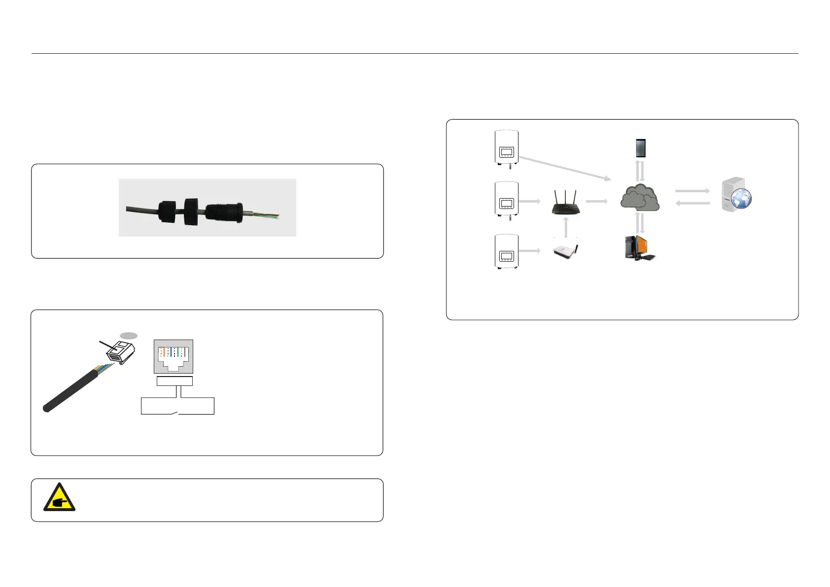
The inverter can be monitored via Wi-Fi or GPRS. All Solis communication devices are
optional. For connection instructions, please refer to the Solis Monitoring Device
installation manuals.
Internet
GPRS monitoring
Wi-Fi monitoring
Smart phone monitoring
PC monitoring
Web server
Router
Wi-Fi monitoring
Wi-Fi box
Figure 4.14 Wi-Fi orGPRScommunication function
4.10 Inverter monitoring connection
NOTE:
To use this function, please contact the manufacturer.
4.9 Logic interface connection
Please follow below steps to assemble RJ45 connector.
1. Insert the network cable into the communication connection terminal of R J45.
Figure 4.12 RJ45 communication connection terminals
2. Use the network wire stripper to strip the insulation layer of the communication cable.
According to the standard line sequence of figure 4.13 connect the wire to the plug of
RJ45, and then use a network cable crimping tool to make it tight.
Correspondence between the cables
and the stitches of plug, Pin5 and Pin6
of RJ45 terminal is used for the logic
interface, other Pins are reserved.
Pin 1: Reserved; Pin 2: Reserved
Pin 3: Reserved; Pin 4: Reserved
Pin 5: Switch_input1; Pin 6: Switch_input2
Pin 7: Reserved; Pin 8: Reserved
1--8
Rj45 plug
Rj45terminal
1 2 3 4 5 6 7 8
1 2 3 4 5 6 7 8
DRM(logic interface)
Switch_ input1 Switch_ input2
Figure 4.13 Strip the insulation layer and connect to RJ45 plug
3. Connect RJ45 to DRM (l ) . ogic interface
Logic interface is required by some local regulations that can be operated by a simple switch
or contactor(Not available in South Africa).
When the switch is closed the inverter can operated normally. When the switch is opened,
the inverter will reduce it’s output power to zero within 5s.
Pin5 and Pin6 of RJ45 terminal is used for the logic interface connection.
.20. .21.

 Loading...