2 . Saf ety & W arn i n g
3 .1 Screen
Soli s R HI seri es adopts LC D screen, i t di splays th e statu s, operati ng i nf orm ati on and
setti ng s of th e i nverter.
3 . O vervi ew
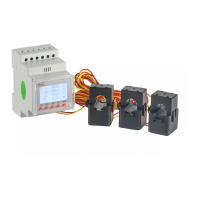
W A R N IN G :
Th e R H I seri es does not su pport parallel ( th ree- an d si ng le-ph ase) operati on
on t h e A C -B A C KUP port . P arallel operati on of t h e u ni t w i ll voi d t h e w arrant y.
W A R N IN G :
P lease ref er t o t h e speci f i cati on of th e batt ery bef ore con f i g u rati on .
2 .3 Not i ce For Use
Th e i n verter h as been con stru cted accordi ng t o th e appli cable saf ety an d t ech ni cal
g u i deli n es. Use t h e i nvert er i n i n stallati ons t h at m eet t h e f ollow i n g speci f i cat i on s O NLY:
1 . P erm anent i nstallati on i s req u i red.
2 . Th e electri cal i n stallati on m u st m eet all t h e appli cable reg u lat i on s an d st an dards.
3 . Th e i n verter m u st be i nst alled accordi n g t o t h e i nst ru cti ons stated i n t h i s m anu al.
4 . Th e i n verter m u st be i nst alled accordi n g t o t h e correct t ech n i cal speci f i cati on s.
.6. .7.
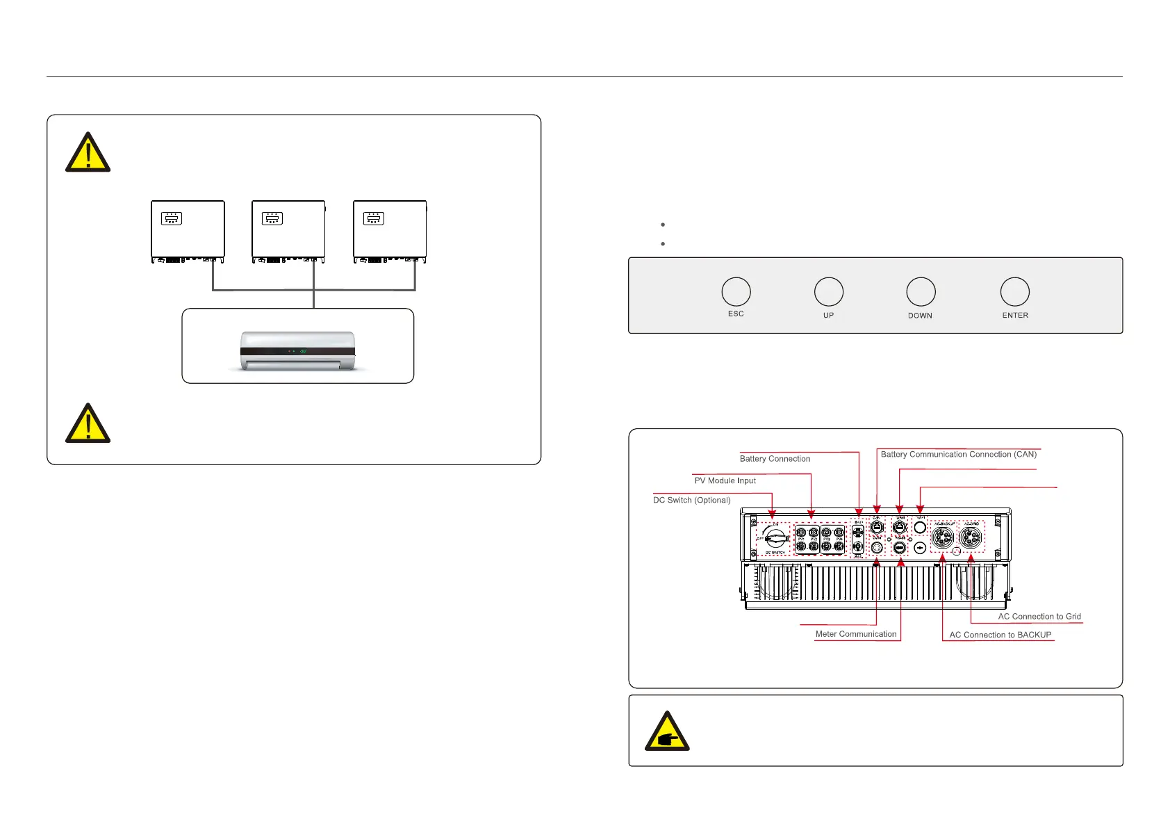
3 .2 Keypad
Th ere are f ou r k eys i n th e f ron t panel of t h e i nvert er ( f rom lef t to ri g h t ) :
E SC , UP, D O W N and E NTE R k eys. Th e k eypad i s u sed f or:
Scrolli ng t h rou g h t h e di splay ed opti ons ( t h e U P and D O W N k eys) ;
A ccess an d m odi f y th e set t i ng s ( th e E SC an d E NTE R k eys) .
Fi g u re 3 .2 Keypad
Soli s R HI seri es i nverter i s di f f erent f rom norm al on-g ri d i nverter, please ref er to th e i nstru cti ons
below bef ore start connecti on.
3 .3 Term i n al C onnect i on
Fi g u re 3 .3 Fron t P an el D i splay
W A R N IN G :
P l e a s e r e f e r t o t h e s p e c i f i c a t i o n o f t h e b a t t e r y b e f o r e c o n f i g u r a t i o n .
3 P h ase LO A D
× ×
D R M C onnect i on
W i Fi C on n ect i on
C O M P ort

 Loading...