4 . Installati on4 . In stallat i on
1 . Mak e su re you u se a cable w i th i n th e correct speci ficati ons as sh ow n i n th e i m ag e below .
D escri be
W i re di am et er 1 3 ~2 5m m
6~1 3 m m ² ( 1 0- 6A W G )
1 3 m m
Traverse cross secti on al area
E xposu re Leng t h
Nu m eri cal valu e
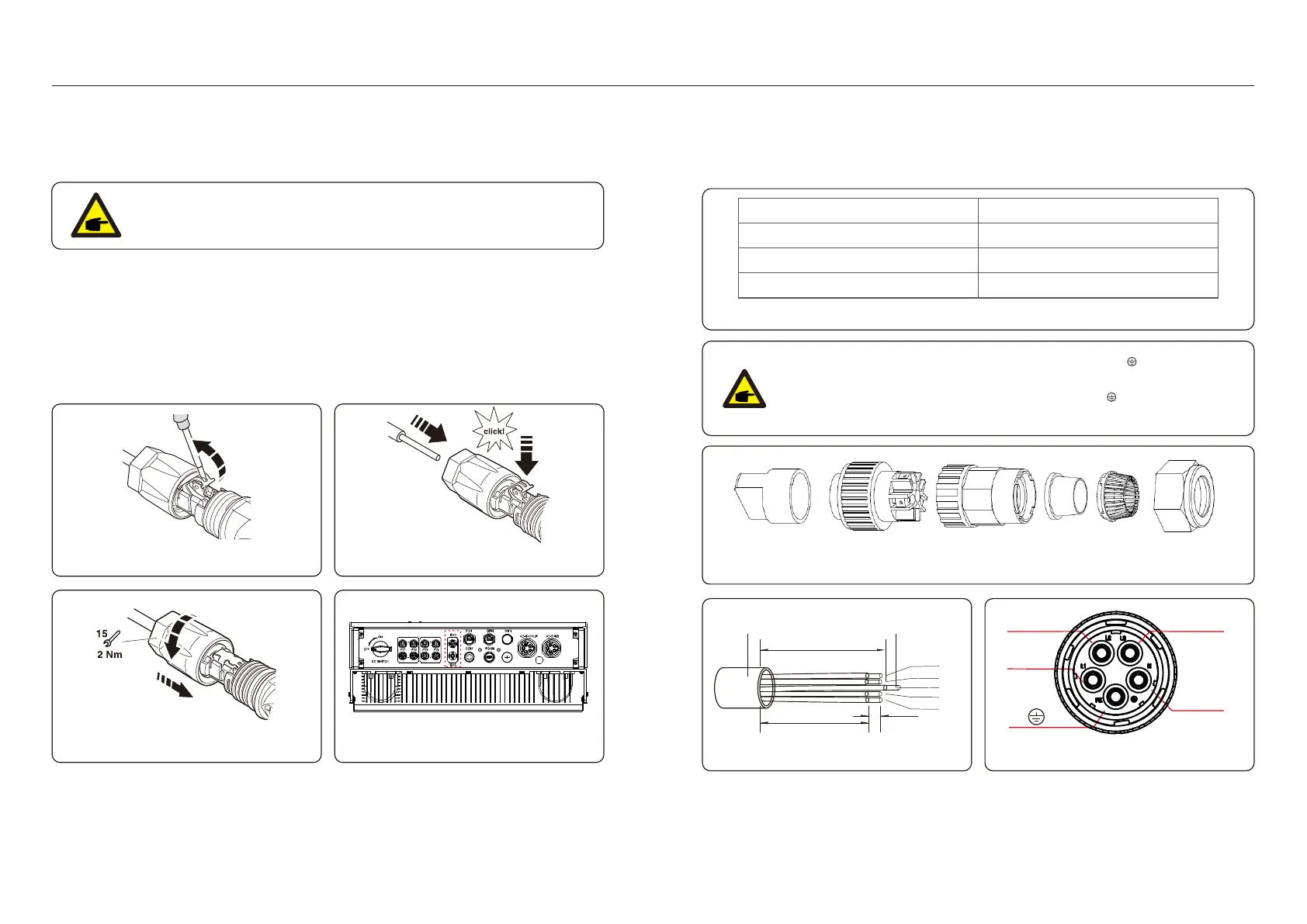
4 .6 B at t ery Term i n al C om pon en ts
Qu i ck connector i s u sed f or battery connecti on. Th e connector i s su i table f or ti n-plated cables
w i th a condu ctor cross secti on of 2 .5-6m m 2 ( A W G 1 4 -1 0) .
Battery cable ou tsi de di am eter rang e: 5.5m m - 8.0m m .
Th ere are tw o A C term i nals and th e assem bly steps f or both are th e sam e.
Tak eou tth eA C connectorpartsf rom th epack ag i ng .
4 .7 A ssem bli ng th eA C C on nect or
N O TE :
A bladed screw dri ver w i th a 3 -m m w i de blade i s req u i red to perf orm th e connecti on.
Step 1 . Stri p 1 5m m of f th e condu ctor u si ng a su i table stri ppi ng tool f or th i s.
Step 2 . O pen th e spri ng u si ng a screw dri ver as below . 9) ( see f i g u re 4 .
Step 3 . Insert th e stri pped w i re w i th tw i sted li tz w i res all th e w ay i n.
Th e w i re ends h ave to be vi si ble i n th e spri ng . A nd th en close th e spri ng . 1 0)( see f i g u re 4 .
Step 4 . P u sh th e i nsert i nto th e sleeve and ti g h ten th e cable g land w i th 2 N.m torq u e. 1 1 )( see f i g u re 4 .
Step 5. Fi t th e connectors to th e battery ports at th e bottom of th e i nverter w i th correct polari ty
and a " cli ck " sou nd. 1 2 )( see f i g u re 4 .
Fi g u re 4 .9 Fi g u re 4 .1 0
A B
C D E F
Fi g u re 4 .1 3 A C con n ect or
In ternal of A C con n ector si g n s " L1 " , " L2 " , " L3 " , " N" and " P E " f i ve conn ect i on
port s ( see Fi g u re 4 .1 5) . Th ree li ve w i res are con n ect ed th e " L1 " , " L2 " an d
" L3 " t erm i nals respect i vely; g rou n d w i re con nects " P E " ; neu tral w i re
con nect s " N" t erm i nal:
Fi g u re 4 .1 1 Fi g u re 4 .1 2
L2
L1
P E
L3
N
O u tsi de-di am et ers
1 3 ~ 2 5m m
C ross-sect i on
6~1 3 m m ²
68m m
70m m
x
x= 1 3 m m
N
L1
L2
L3
Fi g u re 4 .1 4 St ri pped and bared w i re
Fi g u re 4 .1 5 Int ernal stru ct u re of A C con n ect or
P E
Table 4 .1
.1 5..1 4 .
 Loading...