4 . Installati on4 . In stallat i on
4 .4 Mou n t i ng th e Inverter
Th e i n verter sh all be m ou n t ed vert i cally.
Th e st eps to m ou nt t h e i nvert er are li sted below :
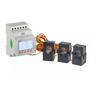
1 . Select th e m ou nt i n g h ei g h t of t h e brack et and m ark t h e m ou nt i n g h oles.
For bri ck w alls, th e posi t i on of t h e h oles sh ou ld be su i table f or t h e expansi on bolt s.
Fi g u re 4 .6 Fi x brack et on th e w all
Fi g u re 4 .7 W all M ou n t B rack et
W A R N IN G :
Th e i n verter m u st be m ou n t ed vert i cally.
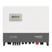
2 . Li f t u p t h e i nvert er ( be caref u l t o avoi d body st rai n ) , and ali g n t h e back brack et on th e
i n vert er w i t h t h e con vex sect i on of th e m ou nti ng brack et. Hang t h e i nvert er on t h e
m ou n ti n g brack et and m ak e su re th e i nvert er i s secu re.
O n ce a su i t able locat i on h as be f ou n d accordi n g ly to 4 .3 u si ng f i g u re 4 .5 and f i g u re 4 .6
m ou nt th e w all brack et to t h e w all.
D i m ensi on s of m ou nti ng brack et :
Fi g u re 4 .5 Invert er w all m ou nti n g
4 .5 P V Inpu t Term i nal A ssem bly
P lease ensu re th e f ollow i ng bef ore connecti ng th e i nverter:
Mak e su re th e voltag e of th e P V stri ng w i ll not exceed th e m ax D C i npu t voltag e ( 1 000Vdc) .
Vi olati ng th i s condi ti on w i ll voi d th e w arranty.
Mak e su re th e polari ty of th e P V connectors are correct.
Mak e su re th e D C -sw i tch , battery, A C-BA CKUP, and A C -G ri d are all i n th ei r of f -states.
Mak e su re th e P V resi stance to g rou nd i s h i g h er th an 2 0K oh m s.
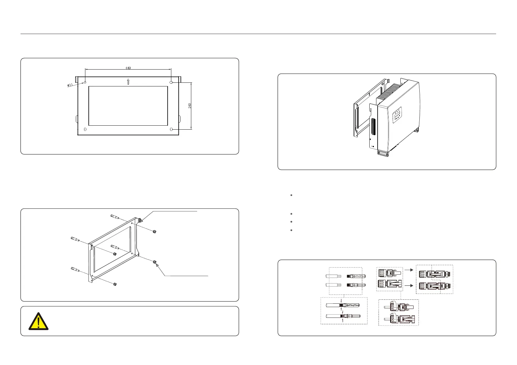
Th e Soli s R HI seri es i nverter u ses th e MC 4 connectors. P lease f ollow th e pi ctu re below to
assem ble th e MC 4 connectors.
P V w i re cross-secti onal area req u i rem ents:2 .5~4 m m ².
B rack et
Su i t able f i xi n g screw s
Fi g u re 4 .8
U s e a p p r o p r i a t e c r i m p i n g
t o o l s f o r c r i m p i n g
n eg ati ve term i nal
posi ti ve term i nal
Inverter term i nal
.1 3 ..1 2 .
 Loading...