4. Installation4. Installation
PE N L
Load_a
Distribution box
CB
CB
RCD
RCD
L
N
PE
Critical Load
Back-up
L
N
PE
L
N
PE
Grid
RS485
L3
L2
L1
GRID
N
PE
CT3
CT2
CT1
B A
9 10 11 12 13 14 15 16 17 18 19 20
Meter
1 2 3 4 5 6 7 8
Voltage
Sampling
Power
CT Wires
Left: Black
Right: White
RCD
RCD
PV strings
CB
Battery
CB
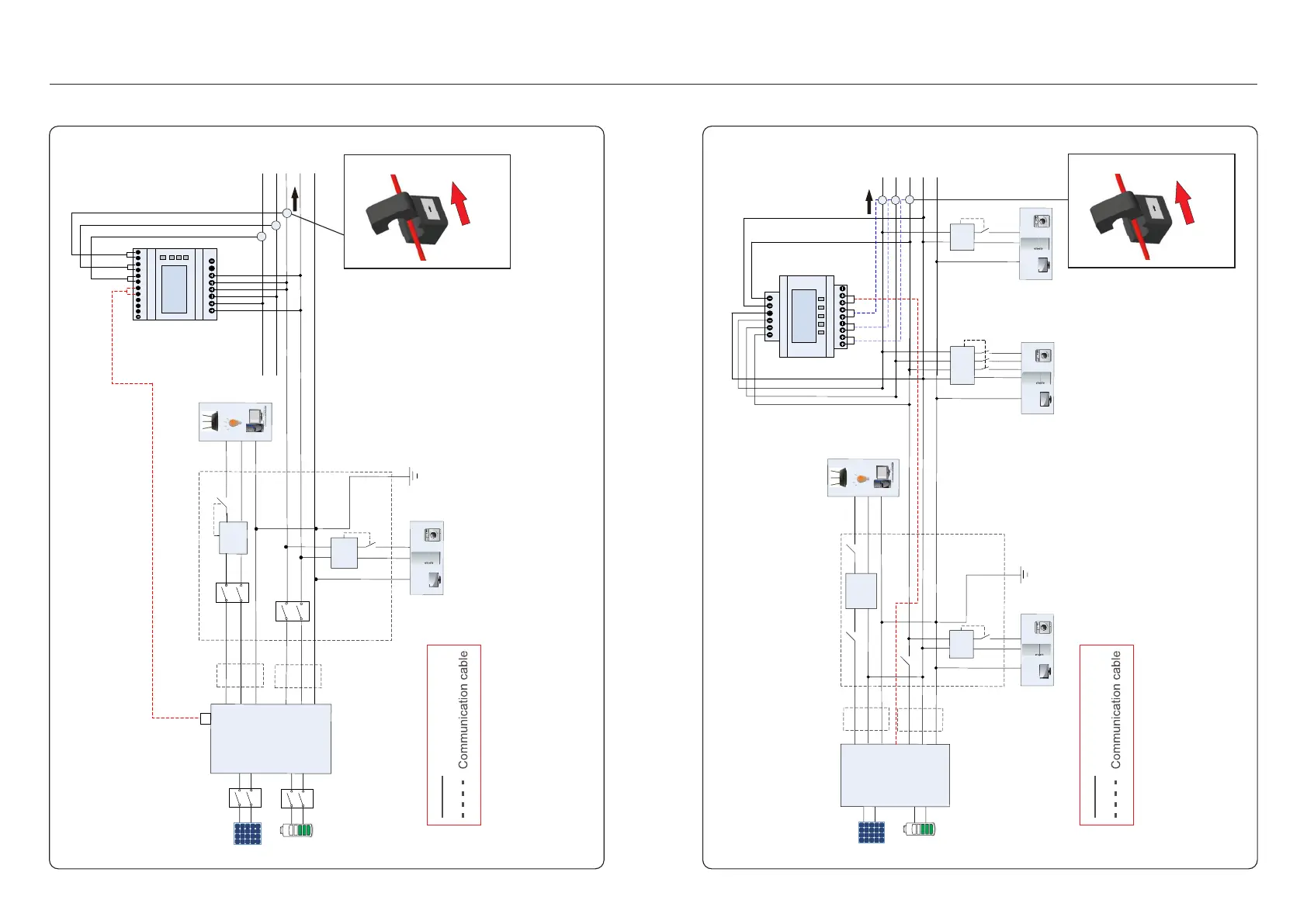
S5-EH1P-L
RS485
Meter
Figure 4.40 (Eastron SDM630MCT)
Critical Load:3kw
PV strings
Battery
S5-EH1P-L
Back-up
L
N
PE
La
N
PE
Grid
Distribution box
RCD
RCD
RS485
PE N L
Load_a
L
N
PE
PE N
La
Load_b
Lb
Lc
PE N Lc
Load_c
RCD
RCD
GRID
RS485
Lc
Lb
La
N
PE
CTc
CTb
CTa
N
La
Lc
Lb
La
N
Meter
1 2 3
4
13
12
5 6 7
8 9
10
21
22
23
A
B
Figure 4.41 (Acrel ACR10R-16DTE4)
.31. .32.
4.8.2 Three phase meter installation
Power cable
Note:
If the CT is installed in the wrong direction,
the Hybrid Inverter can't work normally.
Power cable
Note:
If the CT is installed in the wrong direction,
the Hybrid Inverter can't work normally.
CT direction
towards to grid
G
r
i
d
si
d
e
K L
CT direction
towards to grid
G
r
id
s
i
d
e
K
L

 Loading...