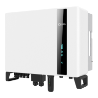
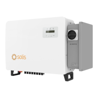
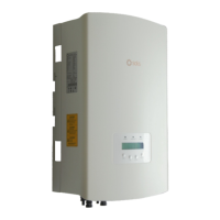
An external ground connection is provided at the right side of inverter.
Prepare OT terminals: M4. Use proper tooling to crimp the lug to the terminal.
Connect the OT terminal with ground cable to the right side of inverter. The torque is 2Nm.
4.3 PE Cable Installation
Figure 4.6 Connect the external grounding conductor
4. Installation4. Installation
Negative terminal
Positive terminal
4.4 PV Input Cable Installation
.12..11.
Before connecting inverter, please make sure the PV array open circuit
voltage is within the limit of the inverter.
Before connection, please make sure the polarity of the output voltage of
PV array matches the“DC+”and“DC-”symbols.
Please use approved DC cable for PV system.
4.0~6.0
4.0(12AWG)
(12~10AWG)
Cable type
Cross section(mm²)
Range
Industry generic PV cable
(model:PV1-F)
Recommended value
1. Select a suitable DC cable and strip the wires out by 7±0.5mm. Please refer to the table
below for specific specifications.
7±0.5mm
2. Take the DC terminal out of the accessory bag, turn the screw cap to disassemble it, and
take out the waterproof rubber ring.
Nut Waterproof collar
Figure 4.7
Figure 4.8

 Loading...


