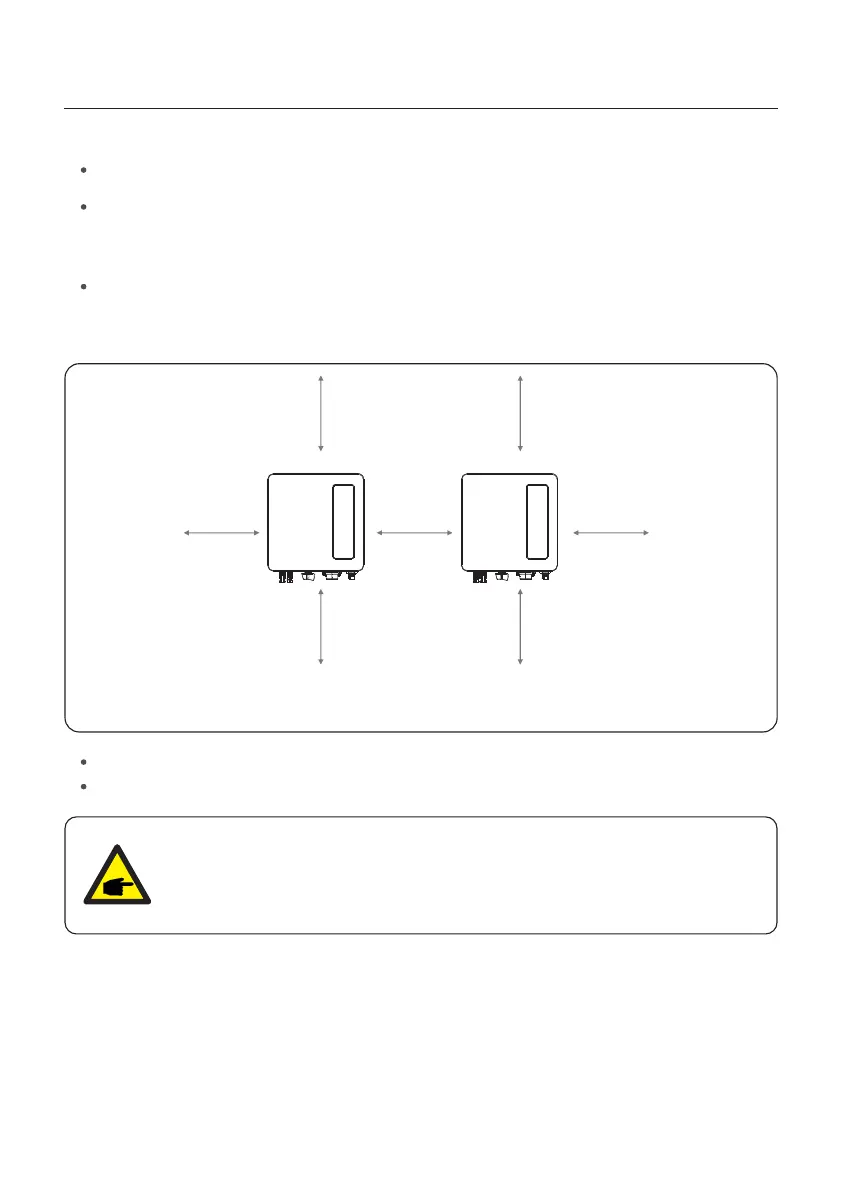
Figure 4.2 Inverter Mounting clearance
Install on a wall or strong structure capable of bearing the weight.
Install vertically with a maximum incline of +/- 5°.If the mounted inverter is tilted to an
angle greater than the maximum noted, heat dissipation can be inhibited, and may result
in less than expected output power.
When 1 or more inverters are installed in one location, a minimum 12inchs clearance
should be kept between each inverter or other object. The bottom of the inverter should
be 20inchs clearance to the ground.
300mm
500mm
500mm
300mm 300mm
300mm
300mm
Visibility of the LED status indicator lights.
Adequate ventilation must be provided if the inverter is to be installed in a confined space.
NOTE:
Nothing should be stored on or placed against the inverter.
4. Installation
User Manual
11
 Loading...