FDEx2 INSTRUCTION MANUAL FDEx2 INSTRUCTION MANUAL
26 +44 (1753) 214 500 sollateksupport@sollatek.com 27
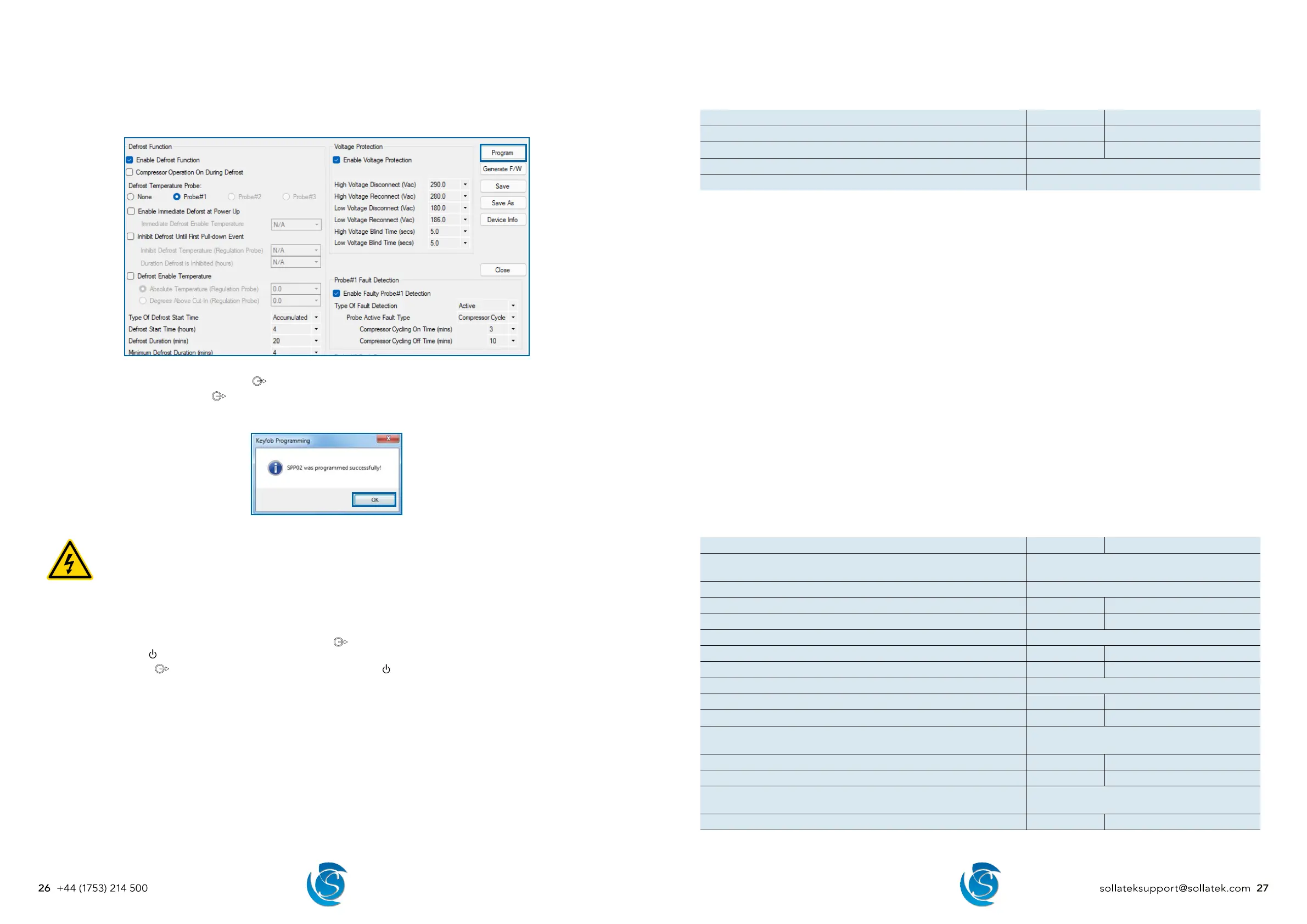
Downloading Parameters from the Parameter Configuration Window.
1. Open and edit/create a configuration to match your requirement.
2. Plug the SPP02 into the USB port in your computer, if plugging in for the first time please wait for all the drivers to be installed
before proceeding, this may take several minutes.
3. Click the Program button in the top right corner of the parameter configuration window.
4. During the programming of the SPP02, the LED on the SPP02 will light up and remain on as the data is being downloaded.
5. On successful downloading, the
LED will start flashing and then turn OFF. A success message will also appear on the
screen.
6. Click OK to close the message box. The SPP02 can now be removed from the computer.
PROGRAMMING THE FDEX2
DANGER! ELECTRIC SHOCK HAZARD - LIVE TERMINAL
This is a non-isolated product. The sensor inputs and outputs are not electrically isolated from the power terminals
therefore the supply MUST be disconnected from the controller before programming the device. This Equipment
is to be serviced by trained personnel only.
1. Connect the mini-USB connector of the SPP02 to the mini-USB port on the extension cable.
2. Remove the bung from the micro-USB port on the FDEx2. Connect the micro-USB connector of the extension cable to the
Micro-USB port on the FDEx2.
3. Press the button on the side of the SPP02 programmer. The
LED will light up and will remain on as the FDEx2 is being
programmed. The
LED on the FDEx2 will also light up.
4. On Completion the
LED will start flashing and turn OFF. The FDEx2 LED will also turn OFF.
5. Unplug the SPP02 and extension cable from the unit. Replace the bung to recover the micro-USB port. Reconnect mains to
the FDEx2. The FDEx2 is now ready for use.
Note: If you have any problems during programming or want to use the SPP Visual software to upload to the SPP02, then please
refer to the SPP02 Visual Programmer User Instructions for more details and troubleshooting.
10. PARAMETERS
10.1 HARDWARE CONFIGURATION
DESCRIPTION UNIT RANGE
Number of Outputs Number 1, 2 or 3
Number of Temperature Probes Number 1 or 2
Enable Door Switch Yes or No
Door Switch Port Selection Probe#2 Input or Prog Port
Number of Outputs
Select the number of connected outputs.
1 = Compressor
2 = Compressor + Aux 1
3 = Compressor + Aux 1 + Aux 2
Number of Temperature Probes
Select the number of connected temperature probes.
1 = Connect regulating probe to P1.
2 = Connect regulating probe to P1 and another probe to P2.
Enable Door Switch
Select whether a door switch is connected.
No = Door switch is disabled.
Yes = Door switch is enabled. You will now be able to set compressor actions based on a door event.
Door Switch Port Selection
Select the port the door switch is connected to on the FDE.
Probe#2 Input = Door switch is connected to P2. Only 1 temperature probe will be available for selection.
Prog Port = Door switch is connected to the micro-USB program port. 2 temperature probes will be available for
selection.
10.2 RELAY CONFIGURATION (RELAY #2/#3)
DESCRIPTION UNIT RANGE
Type of Load
Compressor, Evap Fan, Cond Fan, Light, Heater,
Other
Operation When Compressor is On On, Off, Cycling, Heater
Cycling On Time (mins) Minutes 1 to 255
Cycling Off Time (mins) Minutes 1 to 255
Operation When Compressor is Off On, Off, Cycling, Heater
Cycling On Time (mins) Minutes 1 to 255
Cycling Off Time (mins) Minutes 1 to 255
Operation During Defrost On, Off, Cycling, Heater
Cycling On Time (mins) Minutes 1 to 255
Cycling Off Time (mins) Minutes 1 to 255
Operation When Probe#1 if Faulty
On, Off, Cycling, Heater, On/Cycling, Same as
Comp
Cycling On Time (mins) Minutes 1 to 255
Cycling Off Time (mins) Minutes 1 to 255
Operation When Probe#2 if Faulty
On, Off, Cycling, Heater, On/Cycling, Same as
Comp
Cycling On Time (mins) Minutes 1 to 255