FDEx2 INSTRUCTION MANUAL FDEx2 INSTRUCTION MANUAL
16 +44 (1753) 214 500 sollateksupport@sollatek.com 17
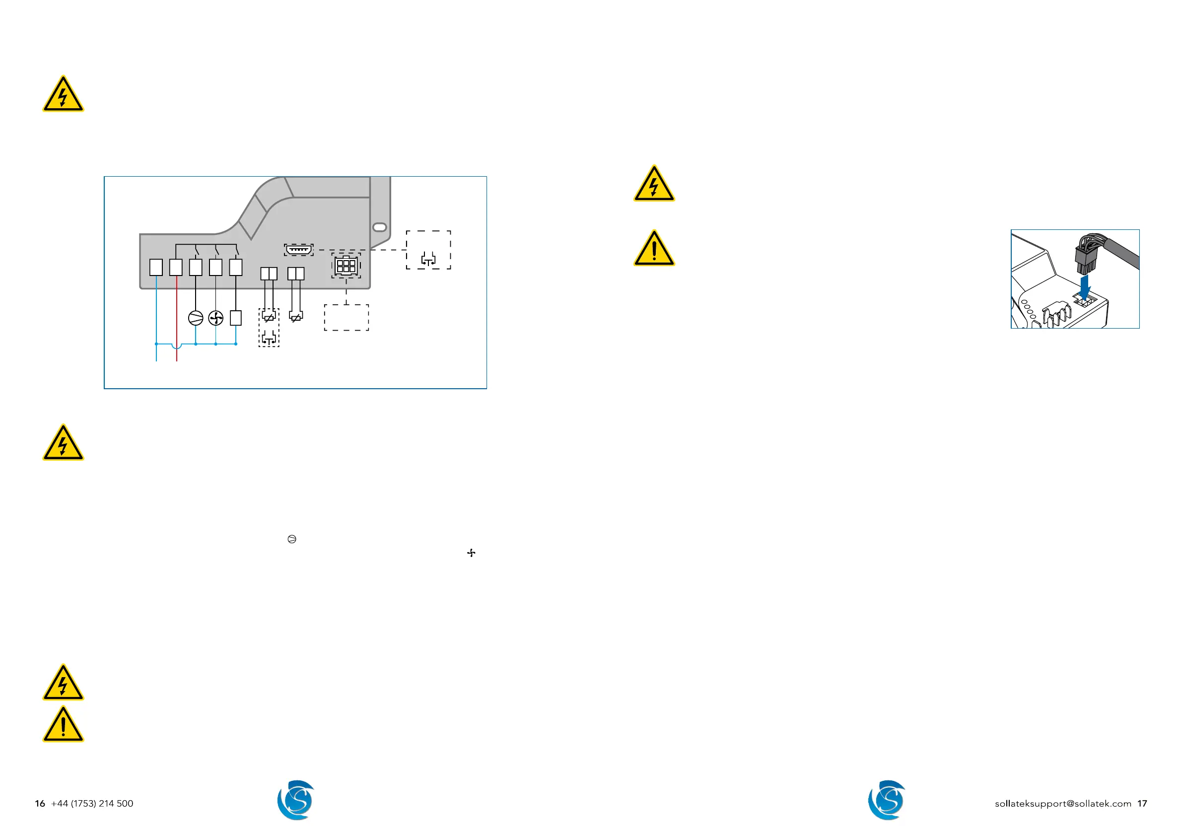
5.4 WIRING CONNECTIONS
DANGER! ELECTRIC SHOCK HAZARD - LIVE TERMINAL
This is a non-isolated product. The sensor inputs and outputs are not electrically isolated from the power terminals
therefore the supply MUST be disconnected from the controller before installing/disconnecting, repairing, or
programming the controller, inputs, outputs, and external devices.
Ensure exposed connectors/wires of connected inputs, outputs and external devices do not touch the frame or
chassis of the cooler or other enclosures otherwise, damage to the controller, equipment, and the cooler will occur.
This equipment is to be installed or serviced by trained personnel only.
OR
NL in
5 A
+-
12345
*
+ -
SPP02
OR
* FDE32 models ONLY
Display OR
GPS Module
5.4.1 MAINS AND OUTPUT WIRING
DANGER! - LIVE TERMINAL
Isolate the supply before installing/disconnecting or repairing the controller. Failure to do so can result in damage
to equipment and electrical shock.
Ensure the connected load does not exceed the maximum relay rating it is connected to and the total current rating
ON at once does not exceed 18 Amps (FDE22/FDE32).
0.25” vertical male spade terminals are used for mains and output connectors. Connections should be made with equivalent
female crimp connectors.
1. Connect the Mains Neutral wire to terminal 1 (marked N) on the FDEx2.
2. Connect the Mains Live-In wire to terminal 2 (marked Lin) on the FDEx2.
3. Connect the Compressor Live wire to terminal 3 (marked
) on the FDEx2.
4. Connect the required output (commonly evaporator fan) Live wire to terminal 4 (Relay #2, marked
) on the FDEx2, if
required.
5. Connect the required output (commonly Lights) Live wire to terminal 5 (Relay #3, marked AUX) of the FDEx2, if required
(FDE32 ONLY)
6. Connect all output Neutrals to Mains Neutral.
Note: Output connectors are based on the default relay configuration, if the output configuration is changed via the FDEx2
configuration interface, then the equipment should be connected accordingly.
5.4.2 INPUT SENSOR WIRING
DANGER! - LIVE TERMINAL
Isolate the supply before installing/disconnecting or repairing the controller. Failure to do so can result in damage
to equipment and electrical shock.
WARNING!
If the probes placed in an accessible area have less than 1.4 mm insulation, then the probes need to be sleeved
(greater than 0.4mm thickness) to attain supplementary insulation.
Separate as much as possible the input sensors and cables carrying inductive load and power. Do Not run power
and signal cables together in the same conduit.
0.11” vertical male spade terminals are used for the P1 and P2 connectors on the FDEx2. Temperature probes and door switch
use a 2-way female crimp terminal connector.
1. Connect the Regulating temperature probe (typically air) to terminal P1 on the FDEx2.
2. Connect a second temperature probe or a door switch to terminal P2 on the FDEx2 as required.
3. Connect a door switch to the Prog port on the FDEx2 if 2 temperature probes and a door switch are required.
Note: The door switch port must be configured by using the configuration interface.
5.4.3 EXTERNAL DEVICE CONNECTION
DANGER! - LIVE TERMINAL
Isolate the supply before connecting/repairing/disconnecting external devices. Failure to do so can result in damage
to equipment and electrical shock.
Do not power the controller with connecting cables unconnected to devices as if exposed connectors were to touch
the frame or chassis of the cooler, damage to the controller, equipment, and the cooler will occur.
WARNING!
Separate as much as possible the input sensors and cables carrying inductive
load and power. Do Not run power and signal cables together in the same
conduit.
1. Insert the 6-way (3x2) connector of the connection cable into the module port on the
FDEx2. Ensure the connector is fully pushed down / securely in the socket.
2. Plug the other end of the connector cable into the device.
5.5 INITIAL STARTUP
5.5.1 CONTROLLER
Once power is supplied to the FDEx2, the FDEx2 will immediately start operating as per the set parameters. The set time delay
will be respected before turning the compressor and other relays ON.
5.5.2 BATTERY MODE TRANSMISSION
To comply with shipping regulations, transmissions on battery mode are disabled, this means the FDEx2 will NOT transmit data
to the portal while being powered by battery until it is enabled.
To enable battery mode transmission, the FDEx2 MUST be powered from mains for a minimum of 5 continuous minutes. After
this period, the FDEx2 will automatically enable this feature.