MPI-506 – USER MANUAL
3.4 Fault loop parameters
NOTE!
If the tested mains includes residual current devices, for the duration of measure-
ment they should be omitted by bypassing. Remember however that bypassing
changes the tested circuit and the results may very slightly differ from the actual
values.
After the measurement, restore the mains to its original state and check operation
of the residual current device. This note does not apply to the earth loop impedance
measurements with the Z
L-PE
RCD function.
Measurements of fault loop impedance performed downstream of inverters are inef-
fective and their results are unreliable. This is due to the instability of internal im-
pedance in inverter circuits during its operation. The measurements of fault loop
impedance should not be performed directly downstream of inverters.
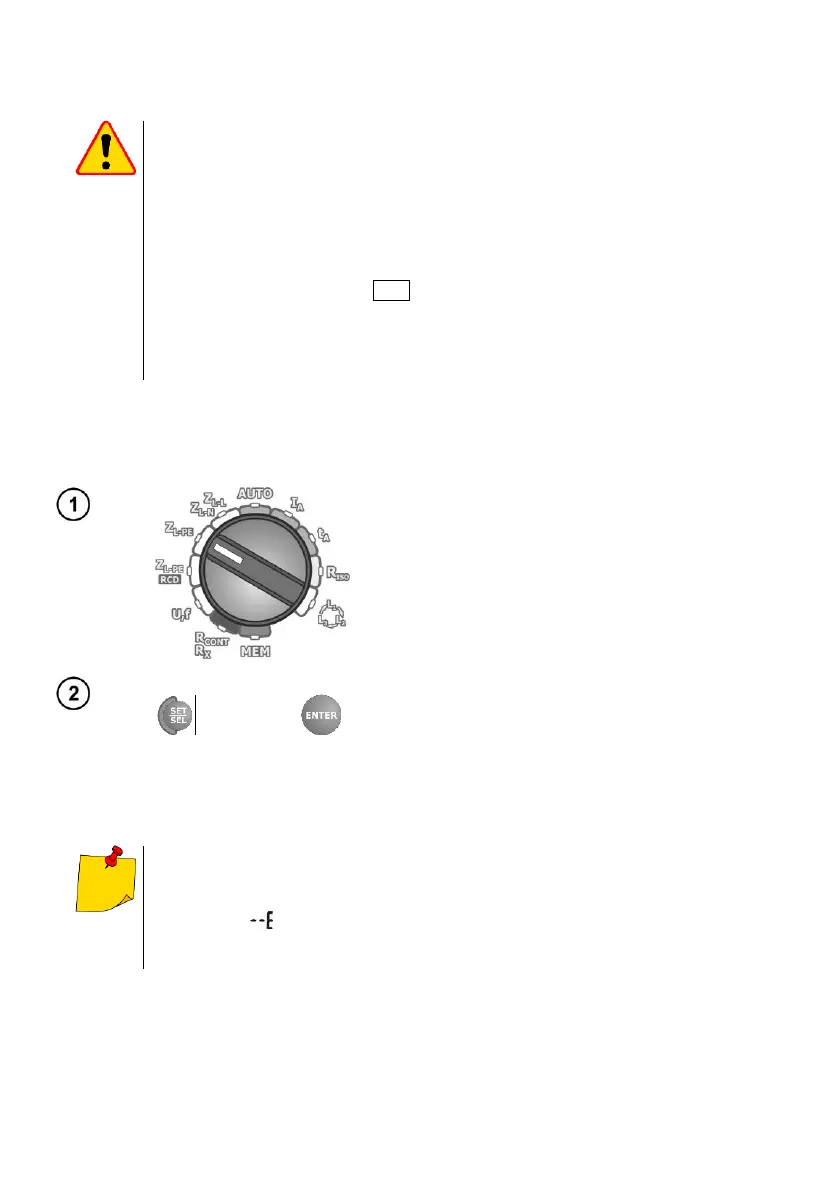
3.4.1 Selecting the lead length
Switch on the meter.
Set the rotary switch to one of the fault loop im-
pedance measurement types.
▪ 1.2 m
▪ 5 m
▪ 10 m
▪ 20 m
Set the parameters according to the following algo-
rithm and the rules for setting the general parame-
ters.
Using original leads and selecting correct length is a guarantee of keeping the de-
clared measuring accuracy.
The WS-03 and WS-04 leads are detected by the meter and you cannot select their
length (the symbol is displayed). When you are using the leads with banana
plugs, before you start the measurements set the correct phase conductor length
complying with the test leads length.