Location and Function of Parts and Controls
14
Protection), a copy protection technology that
incorporates coding technology for digital video signals.
1) The terms HDMI and HDMI High-Definition Multimedia
Interface, and the HDMI Logo are trademarks or
registered trademarks of HDMI Licensing Administrator,
Inc. in the United States and other countries.
The HDMI audio signal is not available for this monitor.
Use HDMI compliant cable (sold separately), Category 2
(High Speed HDMI Cable), with HDMI logo.
DC 12V OUT connector (female)
Supplies the DC power to the controller.
Connect to the DC 12V connector of the controller with
the SMF-17R20 or the cable supplied with the BKM-
37H/38H/39H.
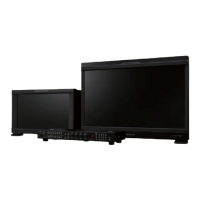
PARALLEL REMOTE connector (RJ-45, 8-pin)
Forms a parallel switch and controls the monitor
externally.
For safety, do not connect the connector for peripheral
device wiring that might have excessive voltage to this
port. Follow the instructions for this port.
Pin assignment
You can assign functions using the [Parallel Remote]
menu (page 61) of the [System Configuration] menu.
Wiring required to use the Remote Control
Connect the function you want to use with a Remote
Control to the Ground (Pin 5).
LAN (10/100) connector
Connect to the LAN (10/100) connector of the
controller by using the SMF-17R20 or the cable supplied
with the BKM-37H/38H/39H. Or connect to the
network or the LAN (10/100) connector of the controller
by using a 10BASE-T/100BASE-TX LAN cable
(shielded-type, sold separately).
CAUTION
For safety, do not connect the connector for peripheral
device wiring that might have excessive voltage to this
port. Follow the instructions for this port.
When you connect the LAN cable of the unit to
peripheral device, use a shielded-type cable to prevent
malfunction due to radiation noise.
The connection speed may be affected by the network
system. This unit does not guarantee the
communication speed or quality of 10BASE-T/
100BASE-TX.
NETWORK switch
LAN: When connecting to the network.
PEER TO PEER: When connecting to the LAN (10/100)
connector of the controller in 1 to 1 connection.
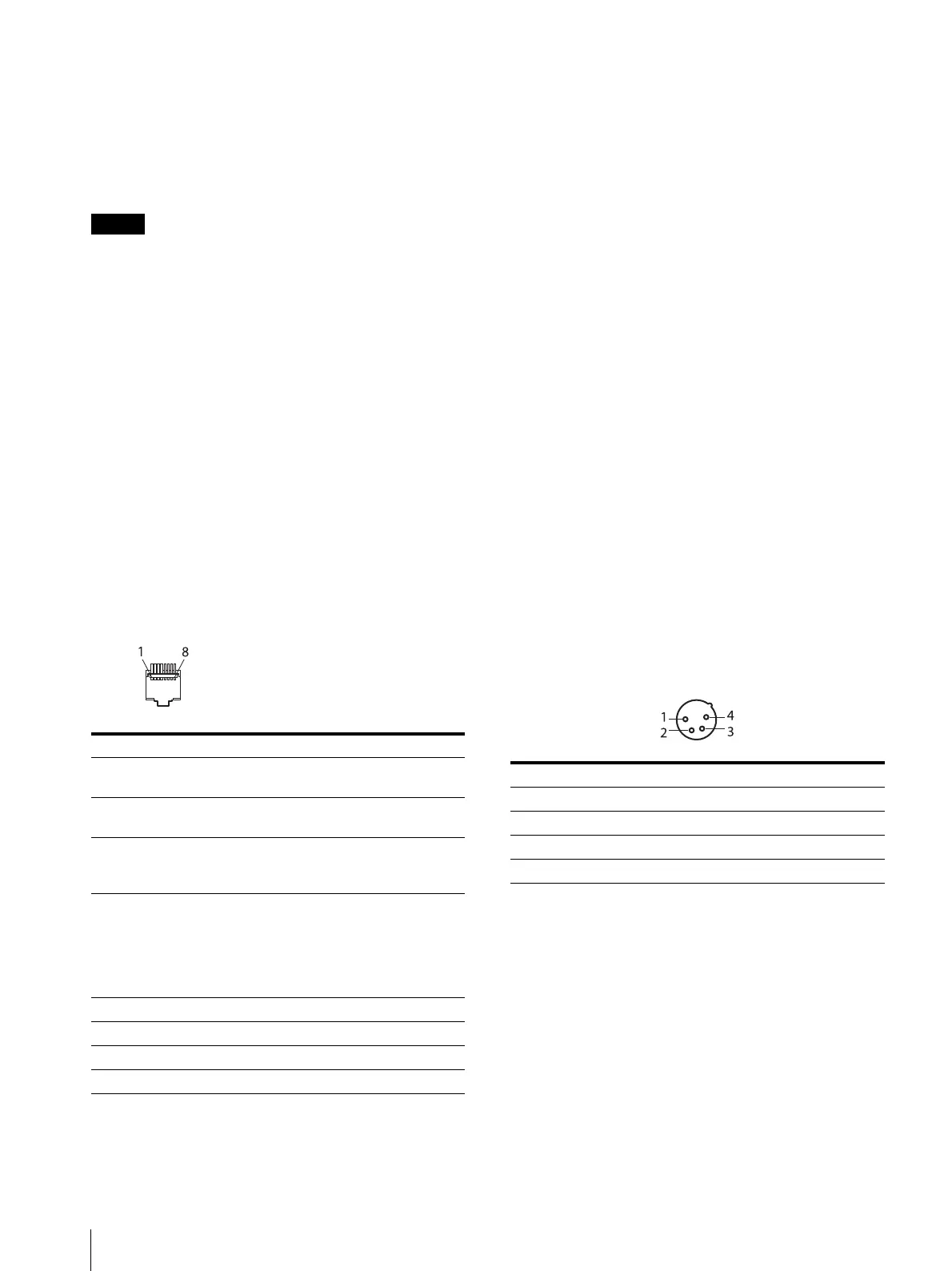
DC IN 24V – 28V (DC power input) connector
(XLR 4-pin, male)
Connect the 24V to 28V DC power supply.
AC IN connector (3-pin)
Connects the monitor to an AC power source, via the
supplied AC power cord.
Power switch
When turned on, the monitor enters operation mode. By
setting in the [Power] menu (page 62) of the [System
Configuration] menu, the monitor can also be set to
enter sleep mode when the power switch is turned on.
Pin number Functions
1 Designating input signal channel 1
(numeric keypad function)
2 Designating input signal channel 2
(numeric keypad function)
3 Marker (set in the [Marker Setting]
menu) On/Off (MARKER button
function)
4 Selecting whether monochrome image
is displayed or the monitor switches the
display mode automatically between
color image and monochrome image
depending on the input signal (MONO
button function).
5GND
6 Not connected
7 Not connected
8 Tally lamp On/Off
Pin number Functions
1– (GND)
2NC
3NC
4 + (DC 24V – 28V)