Adjustment Using the Menus
50
[Butterfly]
Sets the butterfly display.
[Blending]
Sets the blending display.
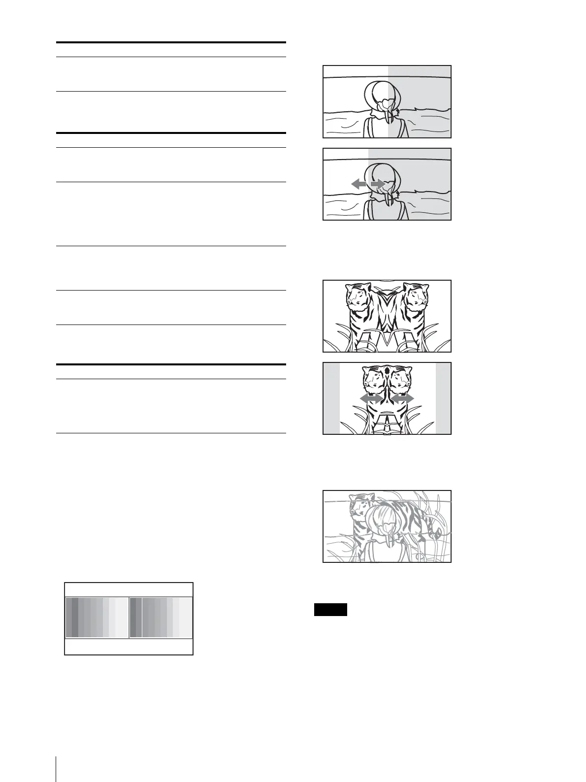
Displaying Two Signals on One Screen
Two input signals are output on the monitor. You can
select the display mode from [Side by Side] (side by
side), [Wipe] (wipe), [Butterfly] (butterfly), and
[Blending] (blending). This is useful for adjusting the
color or comparing two pictures.
You can input the file loaded in the [Capture] menu
(page 54) of the [Function Setting] menu.
[Side by Side] (side by side)
[Wipe] (wipe)
[Butterfly] (butterfly)
[Blending] (blending)
You cannot select the same channel number as
channels for signal A and signal B. Set a different
channel number of the different input for signal A and
signal B.
When the wipe or blending mode is used, signal A and
signal B should be genlocked to synchronize with each
other.
[Position] Sets the position of the boundary line.
Set from –100 (leftward) to +100
(rightward). (Default value: [000])
Submenu Setting
[Line Display] Sets display mode of the boundary line.
[Off]: Not displayed.
[On]: Always displayed.
[Line Color] Sets the boundary line color.
You can select from [White] (white),
[Red] (red), [Green] (green), [Blue]
(blue), [Yellow] (yellow), [Cyan] (cyan)
or [Magenta] (magenta), or [Black]
(black).
[Line Bright] Sets the luminance of the boundary
line.
You can select from [High] (bright) or
[Low] (dark).
[Position] Sets the position of the boundary line.
Set from –100 to +100. (Default value:
[000])
Submenu Setting
[Blending Ratio] Sets the blending ratio when two
images are mixed.
Set from 000% (Signal A disappears) to
100% (Signal B disappears). (Default
value: [050])
Submenu Setting
Signal A Signal B
Two pictures are
displayed side by side.
Signal A Signal B
Left and right pictures
connected at the
boundary position are
displayed.
The boundary line of the
left and right area is
changed with the PHASE
knob of the controller.
Signal A Signal B
The right picture is a left-
right reversal picture of
the left picture.
The display range of the
picture is changed with
the PHASE knob of the
controller.
Signal A and Signal B
A picture that
superimposes signal A
and signal B is displayed.
The mixed ratio of two
input signals is changed
with the PHASE knob of
the controller.