– 14 –
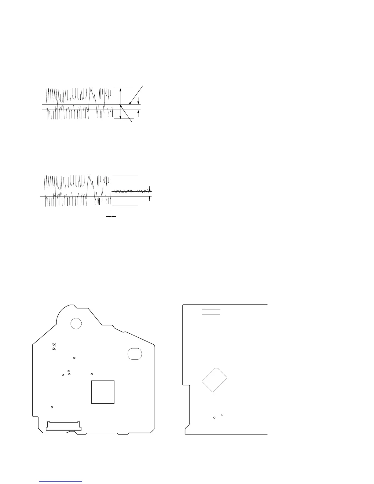
7. Check the level B of the oscilliscope's waveform and the A (DC
voltage) of the center of the Traverse waveform.
Confirm the following :
A/B x 100 = less than ± 22%
Traverse waveform
8. Press the 8 button. (The tracking servo and sledding servo are
turned ON.) Confirm the C (DC voltage) is almost equal to the
A (DC voltage) is step 7.
Traverse waveform
9. Disconnect the lead wire of TP1 (ADJ) connected in step 1.
Adjustment Location :
[BD BOARD] – SIDE A –
0V
level : 1.3 mVp-p
A (DC voltage)
Center of the waveform
B
+ 0.7
– 0.6
0V
C (DC
voltage)
Tracking servo
Sledding servo
OFF
Tracking servo
Sledding servo
ON
CN102
IC101
TP(FEI)
TP(VC)
TP(IOP)
TP(RF)
TP(TE)
TP(FE)
TP
(R151)
CN402
IC302
TP1
(ADJ)
TP2
(AFADJ)
[MAIN BOARD] – CONDUCTOR SIDE –