18
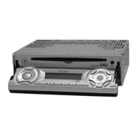
CDX-MP80
• IC501 MB90574CPMT-G-397-BNDE1 (SYSTEM CONTROL) (MAIN BOARD) (US, Canadian model)
• IC501 MB90574CPMT-G-398-BNDE1 (SYSTEM CONTROL) (MAIN BOARD) (AEP, UK model)
Pin No. Pin Name I/O Pin Description
1 – 4 NC O Not used. (Open)
5ATT O System mute control signal output
6 SYS RST O System reset signal output
7NCONot used. (Open)
8 VCC — Power supply pin (+5 V)
9 AMP ATT O Power amplifier mute signal output
10 T.ROM SDA I/O Tuner unit EEPROM data input/output
11 T.ROM SCK O Tuner unit EEPROM clock output
12 NOSE SW/RX I Nose SW detect signal input
13 TX O Flash CPU write-in data output
14 BUS ON O BUS ON control signal output
15 BEEP O Beep signal output
16 TEL ATT I Telephone mute detect signal input
17 UNI SI I SONY BUS data input
18 UNI SO O SONY BUS data output
19 UNI CLK O SONY BUS clock output
20 – 23 NC O Not used. (Open)
24 SIRCS I Wireless remote data input
25 – 30 NC O Not used. (Open)
31 E VOL ATT O Electronic volume mute signal output
32 NC O Not used. (Open)
33 VSS — Ground pin
34 C — Condenser pin for voltage stabilizer
35 CDON IN I CD On signal input
36 NC O Not used. (Open)
37 FSW SFT O OSC frequency shift signal output for DC/DC converter
38 DVCC — Power supply pin (+5 V)
39 DVSS — Ground pin
40, 41 NC O Not used. (Open)
42 AVCC — Power supply pin (+5 V)
43 AVRH — Power supply pin (+5 V)
44 AVRL — Ground pin
45 AVSS — Ground pin
46 KEY IN0 I Key input 0
47 TEMP I Tempareture detect signal input
48 RC IN0 I Rotary commander input 0
49 FP-I DET I Front panel motor current detect signal input
50 QUAL I Tuner noise detction signal input (AEP, UK model)
51 TR-I DET I Tray motor current detect signal input
52 MPTH I Tuner multi-pass detect signal input (AEP, UK model)
53 VSM I S-meter voltage detect signal input
54 VCC — Power supply pin (+5 V)
55 AMP ON O AMP ON control signal output
56 NS MASK O Tuner noise masking control signal output
57 DDC ON O DC/DC converter power control signal output
58 OPEN SENS I Tray open detection signal input
59 CLOSE SENS I Traay close detect signal input
60 LED ON O Tray illumination ON signal output
61 T CLOSE O Tray loading motor output
62 T OPEN O Tray loading motor output
63 VSS — Ground pin
 Loading...