3
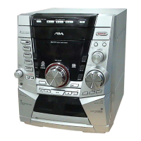
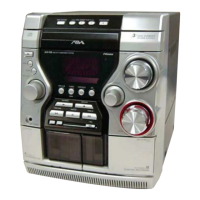
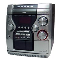
CX-LDB10/LDB20
TABLE OF CONTENTS
1. SERVICING NOTES ................................................ 4
2. GENERAL ................................................................... 5
3. DISASSEMBLY
3-1. Disassembly Flow ........................................................... 7
3-2. Rear Cabinet .................................................................... 7
3-3. Top Panel Assy, Front Panel Assy ................................... 8
3-4. Base Unit (BU-K7BD81B) ............................................. 8
3-5. Mechanical Deck (CMAL5Z220A) ................................ 9
3-6. CONTROL Board ........................................................... 9
3-7. MAIN Board, Power Transformer................................... 10
3-8. Lid (Cassette) ................................................................. 10
4. TEST MODE ............................................................... 11
5. MECHANICAL ADJUSTMENTS......................... 12
6. ELECTRICAL ADJUSTMENTS .......................... 12
7. DIAGRAMS ................................................................. 15
7-1. Block Diagram — CD Section — .................................. 16
7-2. Block Diagram — MAIN Section — ............................. 17
7-3. Printed Wiring Board — CD Board — .......................... 18
7-4. Schematic Diagram — CD Board — ............................. 19
7-5. Printed Wiring Board — MAIN Section (1/2) — .......... 20
7-6. Printed Wiring Board — MAIN Section (2/2) — .......... 21
7-7. Schematic Diagram — MAIN Section (1/3) — ............. 22
7-8. Schematic Diagram — MAIN Section (2/3) — ............. 23
7-9. Schematic Diagram — MAIN Section (3/3) — ............. 24
7-10. Printed Wiring Board — CONTROL Board (1/2) — .... 25
7-11. Printed Wiring Board — CONTROL Board (2/2) — .... 26
7-12. Schematic Diagram — CONTROL Board — ................ 27
7-13. Printed Wiring Board — POWER Board — .................. 28
7-14. Schematic Diagram — POWER Board —..................... 29
7-15. Printed Wiring Board — AUX Section — ..................... 30
7-16. Schematic Diagram — AUX Section — ........................ 30
8. EXPLODED VIEWS
8-1. Overall Section ................................................................ 36
8-2. Front Panel Section ......................................................... 37
8-3. Chassis Section................................................................ 38
8-4. Top Panel Assy ................................................................ 39
9. ELECTRICAL PARTS LIST .................................. 40