34
HCD-CP101
6-18. IC PIN FUNCTION DESCRIPTION
• MAIN BOARD IC801 CXP83124A-055Q (SYSTEM CONTROLLER)
Pin No. Pin Name I/O Description
1
SENSOR
I
Tape end detect sensor input terminal “H”: input when the tape end detected
2
RDS-IN I
Serial data reading clock signal input from the RDS decoder
Used for the AEP, UK models (Except AEP, UK models: not used)
3
SIRCS
I
Remote control signal input from the remote control receiver
4
MOT-CON
O
Capstan/reel motor on/off control signal output terminal “H”: motor on
5
CD-DATA/
TU-DATA
O
Serial data output to the CXD2587Q (at CD function)
PLL serial data output to the tuner pack (at tuner function)
6 T-MODE I
Head position detect switch input terminal “L”: forward direction, “H”: reverse direction
7
REG-CON
O
Main system power supply on/off contorl signal output terminal “H”: power on
8
CD-CLK/TU-
CLK
O
Serial data transfer clock signal output to the CXD2587Q (at CD function)
PLL serial data transfer clock signal output to the tuner pack (at tuner funcion)
9 JOG-C (BASS)
I Jog dial pulse input from the rotary encoder (BASS) (C phase input)
10
SOL-CON O Trigger plunger on/off control signal output terminal “H”: plunger on
11
CD-CLK O Subcode Q data reading clock signal output ti the CXD2587Q (at CD function)
12
SQSO/
RDS-DATA
I
Subcode Q data input from the CXD2587Q (at CD function)
RDS serial data input from the RDS decoder (at tuner function) Used for the AEP, UK models
(Except AEP, UK models: not used)
13 HOLD
O Automatic power control hold signal output to the RF amplifier
14 TRAY-OPEN
OMotor drive siganl output to the loading motor drive “H”: active *1
15 TRAY-CLOSE
OMotor drive signal output to the loading motor drive “H”: active *1
16 JOG-D (BASS)
I Jog dial pulse input from the rotary encoder (BASS) (D phase input)
17
TUNED I Tuning detection signal input from the tuner pack (at tuner function)
18
CD-SENSE/
TU COUNT
I
Internal status (SENSE) input from the CXD2587Q (at CD function)
PLL count data input from the tuner pack (at tuner function)
19
CD-LATCH/
TU CE
O
Serial data latch pulse output to the CXD2587Q (at CD function)
PLL serial chip enable signal output to the tuner pack (at tuner function)
20 JOG-B I
Jog dial pulse input from the rotary encoder (VOLUME) (B phase input)
21 JOG-A I
Jog dial pulse input from the rotary encoder (VOLUME) (A phase input)
22 AMP-MUTE O
Muting on/off control signal output to the power amplifier “H”: muting on
23
VOL-CE O Chip enable signal output for the electrical volume
24 STANDBY LED
I LED drive signal output of the STANDBY indicator (D856) “H”: LED on
25
TU-ON O
Power supply on/off control signal output of the tuner section
LED drive signal output of the BAND indicator “H”: tuner power on (LED on)
26
D. S. G. O LED drive signal output of the DSG (Dynamic Sound Generator) indicator “H”: LED on
27
CD-SYNC
O
LED drive signal output of the CD SYNC indicator “H”: LED on
28
SCK O Serial data transfer clock signal output to the electrical volume
29
JOG-E (TREBLE)
I Jog dial pulse input from the rotary encoder (TREBLE) (E phase input)
30
JOG-F I Jog dial pulse input from the rotary encoder (TREBLE) (F phase input)
31
DC DETECT I Speaker DC output protect signal input terminal
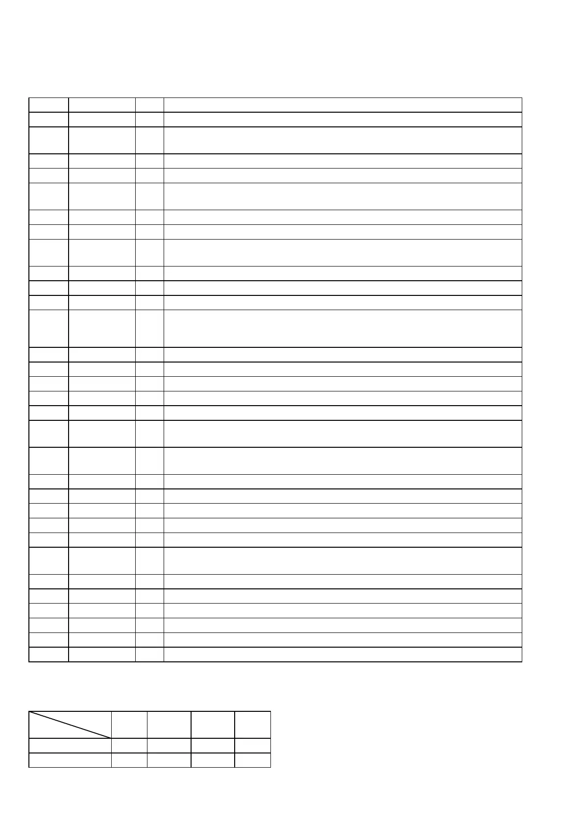
*1 Loading motor control
Stop Table In Table Out Brake
TRAY-OPEN (pin qf)
“L” “L” “H” “H”
TRAY-CLOSE (pin qg)
“L” “H” “L” “H”
Terminal
Mod