8
HCD-FLX5D/FLX7D
Connection:
Procedure:
1. Connect an oscilloscope to test point 1 pin and 3 pin
of CN901 on the MB board.
2. Turn the power on.
3. Put the disc (LUV-P01) (Part No.:4-999-032-01) (CD)
in to playback.
4. Conf
5. Put the disc (TDV-520CSO) (Part No.:J-2501-236-A)
(DVD) in to playback.
6. Perform Comfirmation in the same manner as step 4.
irm that oscilloscope waveform is clear and check RF
signal level is correct or not.
Note: A clear RF signal waveform means that the shape “◊” can be
clearly distinguished at the center of the waveform.
RF signal waveform
+
–
oscilloscope
VOLT/DIV: 200 mV
TIME/DIV: 500 ns
CD: 1.05
±
0.2 Vp-p
DVD: 1.09
±
0.2 Vp-p
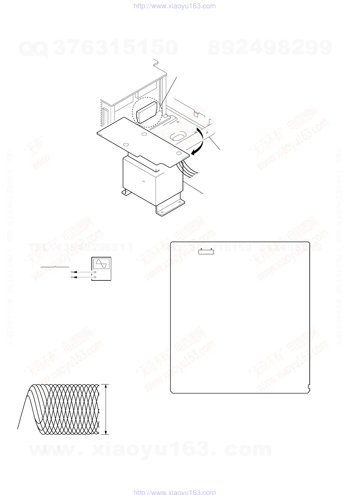
DECISION TO PASS OR FAIL OF THE OPTICAL
PIC-UP BLOCK
CN901 1 pin
CN901 3 pin
MB board
IC501
chassis
power transformer
(T911)
IC501 SERVICE POSITION
•When you check IC501, please move a power trans former (T911) from a chassis.
Checking Location:
– MB BOARD (Component Side) –
71
CN901
w
w
w
.
x
i
a
o
y
u
1
6
3
.
c
o
m
Q
Q
3
7
6
3
1
5
1
5
0
9
9
2
8
9
4
2
9
8
T
E
L
1
3
9
4
2
2
9
6
5
1
3
9
9
2
8
9
4
2
9
8
0
5
1
5
1
3
6
7
3
Q
Q
TEL 13942296513 QQ 376315150 892498299
TEL 13942296513 QQ 376315150 892498299
http://www.xiaoyu163.com
http://www.xiaoyu163.com