EasyManua.ls Logo

Sony HCD-FX900W User Manual

Sony HCD-FX900W
146 pages
To Next Page IconTo Next Page
Page #1 background imageLoading...
Page #1 background image
SERVICE MANUAL
Sony Corporation
Home Audio Division
Published by Sony Techno Create Corporation
US Model
Canadian Model
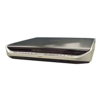
SUPER AUDIO CD/DVD RECEIVER
9-887-193-02
2006I16-1
© 2006.09
Ver. 1.1 2006.09
HCD-FX900W
HCD-FX900W is the amplifier, DVD/CD
and tuner section in DAV-FX900W.
— Continued on next page —
SPECIFICATIONS
Model Name Using Similar Mechanism HCD-FX10
Mechanism Type CDM69EH-DVBU101
Optical Pick-up Name
KHM-310CAB/C2NP
This system incorporates with Dolby* Digital and Dolby Pro
Logic (II) adaptive matrix surround decoder and the DTS**
Digital Surround System.
* Manufactured under license from Dolby Laboratories.
“Dolby,” “Pro Logic,” and the double-D symbol are trademarks
of Dolby Laboratories.
** Manufactured under license from Digital Theater Systems, Inc.
“DTS” and “DTS Digital Surround” are trademarks of Digital
Theater Systems, Inc.
AUDIO POWER SPECIFICATIONS
POWER OUTPUT AND
TOTAL HARMONIC
DISTORTION
(FTC Output Power): FL/FR/SL/SR: 84 W/ch
3 ohms at 160 - 20,000 Hz,
0.7 % THD
SW: 162 W 1.5 ohms at 25
- 160 Hz, 0.7 % THD
C: 84W 3 ohms at 500 -
20,000 Hz, 0.7% THD
Amplifier section
Surround mode (reference)
RMS output power, 10 %
THD
Front: 143 W + 143 W
(with SS-TS55)
Center*: 143 W
(with SS-CT52)
Surround*: 143 W + 143
W** (3 ohms)
Subwoofer*: 285 W
(with SS-WS53)
*Depending on the sound field settings and the source,
there may be no sound output.
** When connecting the surround speakers to the system
by the speaker cords.
Inputs (Analog)
TV/VCR 1, TV/VCR 2 (AUDIO IN)
Sensitivity: 450/250 mV
AUDIO IN Sensitivity: 250/125 mV
Inputs (Digital)
TV/VCR1 (COAXIAL IN)/TV/VCR2 (OPTICAL IN)
impedance: 75 ohms/–
Outputs (Analog)
Phones Accepts low-and high-
impedance headphones.
Super Audio CD/DVD system
Laser Semiconductor laser
(Super Audio CD/DVD:
λ = 650 nm)
(CD: λ = 790 nm)
Emission duration:
continuous
Signal format system NTSC
Tuner section
System PLL quartz-locked digital
synthesizer system
FM tuner section
Tuning range 87.5 – 108.0 MHz
(100 kHz step)
Antenna (aerial) FM wire antenna (aerial)
Antenna (aerial) terminals 75 ohms, unbalanced
Intermediate frequency 10.7 MHz
AM tuner section
Tuning range 530 – 1,710 kHz (with the
interval set at 10 kHz)
531 – 1,710 kHz (with the
interval set at 9 kHz)
Antenna (aerial) AM loop antenna (aerial)
Intermediate frequency 450 kHz
Video section
Outputs VIDEO: 1 Vp-p 75 ohms
S VIDEO:
Y: 1 Vp-p 75 ohms
C: 0.286 Vp-p 75 ohms
COMPONENT:
Y: 1 Vp-p 75 ohms
PB/CB, PR/CR: 0.7 Vp-p
75 ohms
HDMI OUT: Type A (19
pin)
Inputs TV/VCR1: 1 Vp-p
75 ohms
TV/VCR2: 1 Vp-p
75 ohms
COMPONENT:
Y: 1 Vp-p 75 ohms
PB/CB, PR/CR: 0.7 Vp-p
75 ohms

Table of Contents

Question and Answer IconNeed help?

Do you have a question about the Sony HCD-FX900W and is the answer not in the manual?

Sony HCD-FX900W Specifications

General IconGeneral
BrandSony
ModelHCD-FX900W
TypeReceiver
Channels2.1
TunerFM/AM
CD PlayerYes
Disc PlaybackCD, CD-R/RW
USB PlaybackYes
BluetoothYes
Remote ControlYes
Power Output100W
ConnectivityUSB

Summary

SPECIFICATIONS

AUDIO POWER SPECIFICATIONS

Details output power and total harmonic distortion for various speaker configurations.

Video section

Lists video output and input specifications including HDMI and component.

General

Power requirements

Specifies the voltage and frequency for operation.

Dimensions (approx.)

Provides approximate physical dimensions of the unit.

SAFETY CHECK-OUT

LEAKAGE TEST

Describes AC leakage testing procedure and limits.

NOTES ON LASER DIODE EMISSION CHECK

DISC SLOT LOCK

Explains how to lock and unlock the disc tray for anti-theft demonstrations.

Discharge the charged electricity in capacitors to prevent electric shock as follows

Use a resistor of 800 ohms, 2 Watts for discharging the following capacitors.

Safety instruction for discharging capacitors using a specific resistor.

Fix the capacitors with adhesive agent as follows

PRECAUTION WHEN INSTALLING A NEW OP UNIT / PRECAUTION BEFORE UNSOLDERING THE STATIC ELECTRICITY PREVENTION SOLDER BRIDGE

Precautions for installing new optical pick-up units and handling solder bridges.

Precaution when replacing the BUTTON

MAIN board service position (side A)

MAIN board service position (side A)

Visual guide showing the service position of the MAIN board (Side A).

MAIN board service position (side B)

MAIN board service position (side B)

Visual guide showing the service position of the MAIN board (Side B).

DMB12 board service position

DMB12 board service position

Visual guide illustrating the service position of the DMB12 board.

POWER board service position

POWER board service position

Visual guide showing the service position of the POWER board.

SECTION 2 GENERAL

Front panel

Identifies controls and connectors on the front panel of the unit.

Rear panel

Identifies ports and connectors on the rear panel of the unit.

Front panel display

About the indications in the front panel display

Explains the meaning of various indicators on the front panel display.

Remote control

BUTTON DESCRIPTIONS

Lists the functions of various buttons on the remote control.

SECTION 3 DISASSEMBLY

3-1. DISASSEMBLY FLOW

Outlines the step-by-step procedure for disassembling the unit.

SECTION 4 ASSEMBLY

4-1. HOW TO INSTALL THE CAM (EJECT LOCK)

Instructions for installing the cam (eject lock) mechanism.

4-2. HOW TO INSTALL THE CAM (GEAR)

Procedure for installing the cam (gear) component.

SECTION 5 TEST MODE

1. Cold Reset

Clears all RAM data, resetting the system to initial conditions.

2. Panel Test Mode

Mode for checking software version, FL, LED, and KEY status.

3. Disc Tray Lock

Function to lock the disc tray for anti-theft demonstration.

4. DVD Ship Mode

Mode used for returning the set to the customer after repair.

DVD SECTION

8-1. GENERAL DESCRIPTION

Overview of the IOP measurement function for diagnosis and adjustment.

8-2. HOW TO ENTER TEST MODE

Procedure to enter the Test Mode menu for diagnosis.

8-3. EXECUTING IOP MEASUREMENT

Standard procedures for executing IOP measurement.

8-4. EMERGENCY HISTORY

8-4-1. Clear the Laser Hour

Resets laser hour data for both CD and DVD.

8-4-2. Clear the Emergency History

Resets all emergency history error codes.

SECTION 6 ELECTRICAL ADJUSTMENT

DVD SECTION

Procedures for adjustment and measurement when replacing the base unit.

DIAT SECTION

Adjustment procedure for DIAT signal RF level.

SECTION 7 DIAGRAMS

• Circuit Boards Location

Illustrates the physical location of various circuit boards within the unit.

• Waveforms – DMB12 Board –

1 IC101 6 (DVDRFIP)

Waveform for DVDRFIP signal at IC101.

2 IC101 <xx. (XTALI)

Waveform for XTALI signal at IC101.

7 IC101 <x// (YUV4)

Waveform for YUV4 signal at IC101.

– MAIN Board –

0 IC702 ws (XIN(I))

Waveform for XIN(I) signal at IC702.

qa IC2 <zvx (CLKIN)

Waveform for CLKIN signal at IC2.

qs IC501 qg (Xin)

Waveform for Xin signal at IC501.

qd IC3010 rk (XFSOIN)

Waveform for XFSOIN signal at IC3010.

• IC Block Diagrams

– RELAY Board –

IC block diagram for the RELAY board components.

– DMB12 Board –

IC block diagram for DMB12 board components.

– MAIN Board –

IC block diagrams for CXD9883M components on the MAIN board.

– MAIN Board –

IC671 SN74LV126APWR

Logic diagram for IC671, a SN74LV126APWR IC.

IC704 SN74LVC257APWR

Logic diagram for IC704, a SN74LVC257APWR IC.

IC3010, IC3020, IC3030 CXD9876R

Block diagrams for IC3010, IC3020, IC3030, CXD9876R.

SECTION 8 EXPLODED VIEWS

8-1. OVERALL ASSY

Exploded view illustrating the assembly of the main unit components.

8-2. FRONT PANEL ASSY

SECTION 9 ELECTRICAL PARTS LIST

NOTE:

General notes regarding part number differences and availability.

When indicating parts by reference number, please include the board name.

Instruction on how to reference parts in the list.

Related product manuals